EasyManua.ls Logo

Mitsubishi Electric PLK-G2008H User Manual

Mitsubishi Electric PLK-G2008H
69 pages
To Next Page IconTo Next Page
Page #1 background imageLoading...
Page #1 background image
INDUSTRIAL SEWING MACHINE
MODEL
PLK-G2008H
TECHNICAL MANUAL
SEWING MACHINE HEAD
A180E674P04

Table of Contents

Question and Answer IconNeed help?

Do you have a question about the Mitsubishi Electric PLK-G2008H and is the answer not in the manual?

Mitsubishi Electric PLK-G2008H Specifications

General IconGeneral
BrandMitsubishi Electric
ModelPLK-G2008H
CategorySewing Machine
LanguageEnglish

Summary

FOR SAFE USE

Safety Indications Explained

Defines DANGER and CAUTION levels for hazardous conditions.

Caution Symbols Guide

Lists and explains specific caution symbols used in the manual.

SAFETY PRECAUTIONS

Usage Environment Guidelines

Specifies environmental conditions to avoid for safe operation.

Installation Safety Procedures

Provides safety guidelines for installing the sewing machine.

SEWING AND ADJUSTMENT SAFETY

Sewing Operation Safety Tips

Key safety measures to observe during sewing operations.

Adjustment Safety Guidelines

Essential safety measures for machine adjustments.

SEWING OPERATIONS

Core Sewing Procedures

Covers basic sewing, halt switch, teaching, and pre-heating.

Clamp and Trimming Settings

Configuration for alternating clamps and thermal trimming operations.

Thread Tension Adjustment

Detailed steps for adjusting upper and bobbin thread tensions.

STANDARD ADJUSTMENT

Component Alignment Adjustments

Adjustments for shuttle, needle, and presser foot alignment.

Timing and Clearance Settings

Setting needle-shuttle, needle-driver clearances, and timing.

Test Mode and Sensor Checks

Using test mode and checking sensor signals.

Trimming, Tension, and Belt Adjustments

Adjusting trimming components, tension, and timing belts.

Mechanical Positioning and Home Settings

Adjusting home position, discs, and mechanical settings.

SEWING MACHINE STRUCTURE

Main Component Identification

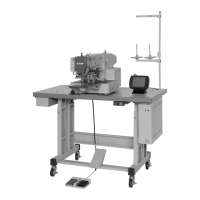
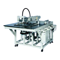
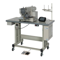
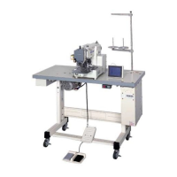
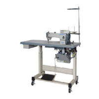
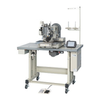
Diagram identifying the primary components of the sewing machine.

TECHNICAL SPECIFICATIONS

Model and Performance Data

Details on model, sewing speed, dimensions, and mass.

System and Component Specs

Information on needles, lubrication, drive systems, and power.

INSTALLATION GUIDE

Table and Stand Preparation

Steps for preparing the table and steel stand for assembly.

Component Installation Procedures

Instructions for installing motor, control box, and operation panel.

INSTALLATION GUIDE (Continued)

Power and Foot Switch Wiring

Wiring and connecting the power and foot switches.

INSTALLATION GUIDE (Continued)

Oil Pan and Head Mounting

Mounting the oil pan and sewing machine head.

INSTALLATION GUIDE (Continued)

V-Belt and Cable Connections

Installing the V-belt and connecting electric cables.

INSTALLATION GUIDE (Continued)

Cable Management and Securing

Fixing and organizing cables with clips and staples.

INSTALLATION GUIDE (Continued)

Belt Cover and Thread Stand Installation

Attaching belt cover and assembling thread stand.

INSTALLATION GUIDE (Continued)

Air Tube Connection Procedure

Connecting the air tubes for the pneumatic system.

LUBRICATION PROCEDURES

Lubrication Points and Safety

Identifying lubrication points and safety during oiling.

PROPER OPERATION

Initial Control Box and Table Settings

Setting model/language and initializing the setting table.

PROPER OPERATION (Continued)

Setting Table and Step File Loading

Loading setting and step files from USB memory.

PROPER OPERATION (Continued)

Creating Configuration USB Memory

Guide to creating a USB memory for initial configuration.

PROPER OPERATION (Continued)

USB Memory Data Transfer

Steps for copying configuration data to USB memory.

PROPER OPERATION (Continued)

Needle Installation Safety

Procedure for safely installing or replacing the needle.

PROPER OPERATION (Continued)

Upper Threading Guide

Instructions for threading the upper thread correctly.

PROPER OPERATION (Continued)

Bobbin Thread Winding Process

Steps for winding thread onto the bobbin.

PROPER OPERATION (Continued)

Bobbin Setting Procedure

Guide to removing and setting the bobbin correctly.

SEWING OPERATIONS

Basic Sewing and Halt Control

Operating the machine, halt switch, and teaching functions.

Clamp and Trimming Settings

Managing pre-heating, clamps, and thermal trimming.

Thread Tension Adjustment

Detailed steps for adjusting upper and bobbin thread tensions.

SEWING OPERATIONS (Continued)

Cancelling Sewing and Jogging

How to cancel sewing and adjust start position.

Teaching Operation Specifics

Specifics on pattern input and thermal trimming codes.

SEWING OPERATIONS (Continued)

Pre-heating Control Logic

Understanding pre-heating behavior based on function codes.

Alternating Clamp Setup

Setting up left/right alternating clamp functionality.

SEWING OPERATIONS (Continued)

Clamp Priority and Step Movement Settings

Configuring clamp priority and step clamp movement.

Input/Output Signal Mode Settings

Setting input signals for I/O customization.

SEWING OPERATIONS (Continued)

Thermal Trimming Operation Switches

Switch usage for manual/test mode and thermal trimming.

SEWING OPERATIONS (Continued)

Thread Tension Adjustment Details

Adjusting bobbin and upper thread tensions for balance.

STANDARD ADJUSTMENT

Shuttle and Needle Alignment

Adjusting shuttle position and aligning needle with shuttle.

Needle Bar Height and Clearance

Setting needle bar height and needle-shuttle clearance.

STANDARD ADJUSTMENT (Continued)

Needle-Shuttle and Needle-Driver Clearances

Fine-tuning clearances between needle, shuttle, and driver.

STANDARD ADJUSTMENT (Continued)

Test Mode Operation Entrance

How to enter the test mode for diagnostics.

Needle-to-Driver Clearance

Setting clearance between needle and driver guard.

STANDARD ADJUSTMENT (Continued)

Test Mode Key Functions and Signals

Understanding test mode keys and checking input signals.

Test Mode Troubleshooting

Steps to resolve issues encountered in test mode.

STANDARD ADJUSTMENT (Continued)

Test Mode Key Functionality

Detailed functions of keys in test mode for trimming equipment.

STANDARD ADJUSTMENT (Continued)

Thermal Trimming Sequence and Conditions

Order of operations and conditions for thermal trimming.

STANDARD ADJUSTMENT (Continued)

Input Signal Status Verification

Confirming ON/OFF status of various input signals.

STANDARD ADJUSTMENT (Continued)

Presser Foot and Shaft Adjustment

Adjusting the driving shaft arm and presser foot position.

STANDARD ADJUSTMENT (Continued)

Presser Foot Sensor and Tension Release

Setting presser foot cylinder sensor and tension release.

STANDARD ADJUSTMENT (Continued)

Upper Thread Thermal Trimming Setup

Steps for setting the thread puller for trimming.

STANDARD ADJUSTMENT (Continued)

Thickness Detector and Thread Wiper Settings

Configuring thickness detector and thread wiper.

STANDARD ADJUSTMENT (Continued)

Upper Thread Heater Adjustment

Positioning the upper thread heater and checking sensors.

STANDARD ADJUSTMENT (Continued)

Lower Thread Trimmer Heater Adjustment

Adjusting the lower thread trimmer heater and sensors.

STANDARD ADJUSTMENT (Continued)

Bobbin Winder and Work Holder Adjustments

Adjusting bobbin thread amount and work holder pressure.

STANDARD ADJUSTMENT (Continued)

Spring Tension and Position Disc Adjustments

Adjusting thread take-up spring tension and position discs.

STANDARD ADJUSTMENT (Continued)

Hook Position and Mechanical Home Settings

Checking hook position and adjusting mechanical home position.

STANDARD ADJUSTMENT (Continued)

X and Y Axis Mechanical Home Position

Adjusting the home position for X and Y axes.

STANDARD ADJUSTMENT (Continued)

X-Y Timing Belt Tension Adjustment

Adjusting tension for X and Y axis timing belts.

STANDARD ADJUSTMENT (Continued)

X-Axis Timing Belt Tension

Procedure for adjusting the X-axis timing belt tension.

Y-Axis Timing Belt Tension

Procedure for adjusting the Y-axis timing belt tension.

MAINTENANCE

Cleaning Procedures and Recommendations

Instructions for cleaning parts and recommended lubricants.

Waste Oil Disposal Guidelines

Proper methods for disposing of waste oil.

TROUBLESHOOTING GUIDE

Thread Breakage Causes and Fixes

Causes and corrective actions for frequent thread breakage.

Upper Thread Pull-Out Issues

Troubleshooting problems with upper thread pulling out.

TROUBLESHOOTING GUIDE (Continued)

Trimming Function Malfunctions

Resolving problems with trimming functions not working.

Bobbin and Stitching Problems

Issues with bobbin removal and skipped stitches.

TROUBLESHOOTING GUIDE (Continued)

Stitch Formation and Machine Operation Issues

Troubleshooting loose stitches and machine non-operation.

Position and Work Holder Problems

Resolving problems with home position and work holder.

TROUBLESHOOTING GUIDE (Continued)

Sewing Pattern Distortion Issues

Addressing issues causing distorted sewing patterns.

APPENDIX: WIRING DIAGRAMS

Connecting Wires Chart

Mapping of solenoid signals and connections.

Control Box and Sensor Wiring

Diagrams for control box and sensor connections.

APPENDIX: POWER SWITCH WIRING

Power Switch to Relay Wiring

Wiring diagrams for power switch to relay across voltage configurations.

APPENDIX: I/O TABLE

Input Signal Assignments

Table detailing input terminal signals and their functions.

Output Signal Assignments

Table detailing output terminal signals and their functions.

APPENDIX: EXPANDED I/O PORT

Expanded I/O Port Overview and Wiring

Description and wiring diagram for the expanded I/O port.

Connector Pinout Diagrams

Diagrams of TE2 and TE1 connector pinouts.

APPENDIX: EXPANDED I/O PORT (Continued)

Connector Pin Assignments Details

Detailed pin numbers for various connectors (CON1, SEN1, SEN2, CON N).

APPENDIX: EXPANDED I/O PORT (Continued)

TE2 Input and TE1 Output Specifications

Specifications for TE2 input and TE1 output ports.

APPENDIX: TRIMMING TIME CHART

Trimming Sequence Timing Overview

Time chart illustrating the sequence of trimming operations.

APPENDIX: TABLE ASSEMBLY

Table Cut-out Dimensions and Components

Diagram of table cut-outs and list of table/stand parts.

APPENDIX: ANAEROBIC ADHESIVE USE

Parts Requiring Anaerobic Adhesive

Identification of parts requiring anaerobic adhesive for assembly.

Related product manuals