Do you have a question about the Mitsubishi Electric PLK-E SERIES and is the answer not in the manual?
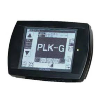
The main display showing pattern information and operational controls.
Displays common keys and their functions for operation.
Procedure for reading patterns from a floppy disk.
Procedure for writing patterns to a floppy disk.
Procedure for deleting patterns from a floppy disk.
Procedure for reading patterns from internal memory.
Procedure for writing patterns to internal memory.
Procedure for deleting patterns from internal memory.
Expedited method for accessing previously read internal memory patterns.
Illustrates the sequence for inputting a basic pattern.
Illustrates the sequence for inputting code data for a pattern.
Illustrates the sequence for inputting an arc pattern.
Illustrates the sequence for inputting a circle pattern.
Illustrates the sequence for inputting a curve pattern.
Illustrates the sequence for inputting a broken line pattern.
Visual representation of a zig zag pattern.
Illustrates the sequence for inputting a split pattern.
Explains the needle stop and trim function upon pressing the halt switch twice.
Displays errors related to power status and halt switch.
Lists error codes that require specific troubleshooting or system reset.
Diagram of external connections for the control box.
Pin assignments for the main motor connector.
Pin assignments for the control box main power supply connector.
Pin assignments for the stepping motor connector.
Pin assignments for the solenoid output connector.
Pin assignments for the RS-232C connector.
Pin assignments for the foot switch connector.
Pin assignments for the teaching panel connector.
Pin assignments for the input signal connector.
Explains the usage of input/output signals via the CONG connector.
Details connections for Terminal 1 into the sewing machine head.
Details connections for Terminal 2 into the sewing machine head.
Table showing signal connections between CPU and PMD.
Table showing signal connections between PMD and FDD.
Table showing signal connections between XC-E and the main motor.
Table detailing PMD to XC-B (CON5) connections.
Table detailing PMD to XC-E (CON6) connections.
Table showing signal connections between CPU and FDD.
Table showing signal connections between CPU and the display.
Table showing signal connections between CPU and XC-B.
Table showing PMD to Transformer connections.
Table showing PMD to Transformer connections (cont.).
Table showing XC-E to Transformer (CO5) connections.
Table showing XC-E to Transformer (CO6) connections.
Table showing XC-E to CONB connections.
Table showing XC-E to Break Register connections.
| Data Storage | CompactFlash card |
|---|---|
| Operation Panel | LCD touch panel |
| Power Supply | Single-phase 200-240V |
| Air Pressure | 0.49MPa |
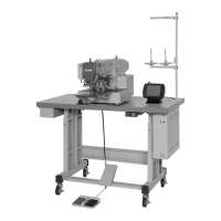
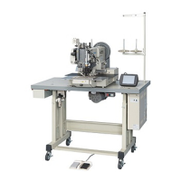
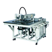
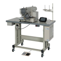
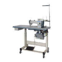
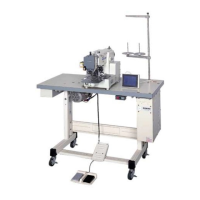
| Type | Programmable Electronic Pattern Sewing Machine |