EasyManua.ls Logo

Mitsubishi Electric PUH-P140YHA User Manual

Mitsubishi Electric PUH-P140YHA
104 pages
To Next Page IconTo Next Page
Page #1 background imageLoading...
Page #1 background image
SERVICE MANUAL
CONTENTS
1. TECHNICAL CHANGES
.................................
3
2. REFERENCE MANUAL
..................................
4
3. SAFETY PRECAUTION
..................................
5
4. FEATURES
......................................................
8
5. SPECIFICATIONS
...........................................
9
6. DATA
.............................................................
11
7. OUTLINES AND DIMENSIONS
....................
15
8. WIRING DIAGRAM
.......................................
19
9. WIRING SPECIFICATIONS
..........................
23
10.
REFRIGERANT SYSTEM DIAGRAM
...............
28
11. TROUBLESHOOTING
...................................
30
12. FUNCTION SETTING
....................................
66
13. DISASSEMBLY PROCEDURE
.....................
73
14. PARTS LIST
..................................................
82
15. RoHS PARTS LIST
.......................................
88
No.OC379
REVISED EDITION-F
SPLIT-TYPE, HEAT PUMP AIR CONDITIONERS
SPLIT-TYPE, AIR CONDITIONERS
R410A
April 2012
Outdoor unit
[Model names]
PU-P71VHA PUH-P71VHA
PU-P71YHA PUH-P71YHA
PU-P100VHA PUH-P100VHA
PU-P100YHA PUH-P100YHA
PU-P125YHA PUH-P125YHA
PU-P140YHA PUH-P140YHA
PU(H)-P71VHA(1).UK PU(H)-P71VHA#2.UK
PU(H)-P71YHA
(1).UK PU(H)-P71YHA#2.UK
PU(H)-P100VHA
(1).UK PU(H)-P100VHA#2.UK
PU(H)-P100YHA
(1).UK PU(H)-P100YHA#2.UK
Note:
This manual describes only
service data of the outdoor
units.
RoHS compliant products
have <G> mark on the spec
nameplate.
For servicing of RoHS com-
pliant products, refer to the
RoHS Parts List.
Revision:
PU(H)-P125/140YHAR4.UK
have been added in
REVISED EDITION-F.
Some descriptions have
been modified.
Please void OC379
REVISED EDITION-E.
[Service Ref.]
Service Ref. is on page 2.

Table of Contents

Question and Answer IconNeed help?

Do you have a question about the Mitsubishi Electric PUH-P140YHA and is the answer not in the manual?

Mitsubishi Electric PUH-P140YHA Specifications

General IconGeneral
BrandMitsubishi Electric
ModelPUH-P140YHA
CategoryAir Conditioner
LanguageEnglish

Summary

1 TECHNICAL CHANGES

2 REFERENCE MANUAL

2-1. INDOOR UNIT’S SERVICE MANUAL

Lists service manuals for indoor units.

2-2. TECHNICAL DATA BOOK

Provides technical data book information.

3 SAFETY PRECAUTION

3-1. ALWAYS OBSERVE FOR SAFETY

General safety instructions before accessing circuits.

3-2. CAUTIONS RELATED TO NEW REFRIGERANT

Specific cautions for R410A refrigerant handling.

4 FEATURES

5 SPECIFICATIONS

6 DATA

6-1. REFILLING REFRIGERANT CHARGE (R410A : kg)

Refilling refrigerant charge data by piping length.

6-2. COMPRESSOR TECHNICAL DATA

Technical data for compressors, including winding resistance.

7 OUTLINES AND DIMENSIONS

1 FREE SPACE (Around the unit)

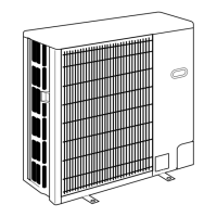
Required free space around the unit for operation.

2 SERVICE SPACE

Required space for service access.

3 FOUNDATION BOLTS

Details on foundation bolts for unit installation.

4 PIPING-WIRING DIRECTIONS

Information on piping and wiring connection directions.

8 WIRING DIAGRAM

9 WIRING SPECIFICATIONS

9-1. FIELD ELECTRICAL WIRING (power wiring specifications)

Specifications for field electrical wiring and power supply.

9-2. SEPARATE INDOOR UNIT/ OUTDOOR UNIT POWER SUPPLIES

Wiring patterns for separate indoor/outdoor unit power supplies.

9-3. INDOOR – OUTDOOR CONNECTING CABLE

Specifications for indoor to outdoor unit connecting cables.

9-4. M-NET WIRING METHOD

Guidelines for M-NET wiring, including grounding and cable types.

10 REFRIGERANT SYSTEM DIAGRAM

11 TROUBLESHOOTING

11-1. TROUBLESHOOTING

Summary of error code display and actions.

11-2. CHECK POINT UNDER TEST RUN

Checks to perform before and during test run.

11-3. HOW TO PROCEED "SELF-DIAGNOSIS"

Procedures for self-diagnosis of the unit.

11-3-3. Remote Controller Diagnosis

Diagnosing issues with the remote controller.

11-3-4. Malfunction-diagnosis method by wireless remote controller

Malfunction diagnosis using a wireless remote controller.

12 FUNCTION SETTING

12-1. UNIT FUNCTION SETTING BY THE REMOTE CONTROLLER

Setting unit functions using the remote controller.

13 DISASSEMBLY PROCEDURE

1. Removing the service panel and top panel

Steps to remove the service panel and top panel.

2. Removing the fan motor (MF)

Steps to remove the fan motor.

3. Removing the electrical parts box

Steps to remove the electrical parts box.

4. Removing the thermistor <Outdoor 2-phase pipe> (TH6)

Steps to remove the outdoor 2-phase pipe thermistor.

5. Removing the thermistor <Outdoor pipe> (TH3) and thermistor <Discharge> (TH4)

Steps to remove outdoor pipe and discharge thermistors.

7. Removing the four-way valve

Steps to remove the four-way valve.

8. Removing the linear expansion valve

Steps to remove the linear expansion valve.

9. Removing the high pressure switch (63H)

Steps to remove the high pressure switch.

10. Removing the motor for compressor (MC)

Steps to remove the compressor motor.

11. Removing the Accumulator

Steps to remove the accumulator.

14 PARTS LIST ( non-RoHS compliant )

15 RoHS PARTS LIST

Related product manuals