–10–
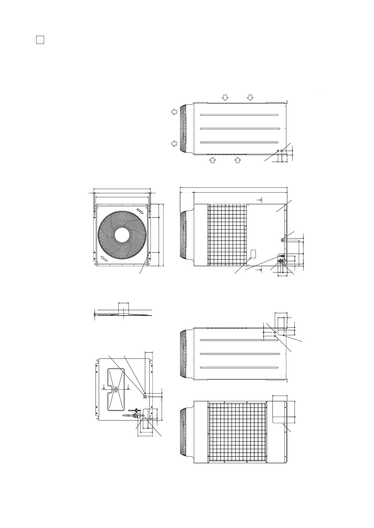
3 EXTERNAL DIMENSIONS
• Models PUH-P200MYA/P250MYA
65
60
84
100 251
234
60 75
194
10048
80 40
121
50
6 5
840
910
15
880
15
990
215
215
560
1715
225
1490
413
55
190
149
40
70
16531
80
79
55
378
160
25
198
237
8073
Service panel
4-14X20 holes
<For mounting
anchor bolt M8>
(Field supply)
Plane view
Rear view
Left side view
Front view
Right side view
Refrig. service
valve (liquid)
φ
12.7<flare>
Refrig. service
valve(gas)
<flange>
φ
38.1 Knockout hole
<Bottom side hole for
the power supply>
φ
38.1 Knockout hole
<Left side hole for
the power supply>
Knockout hole
<Front side hole for
the power supply and
control wiring>
φ
38.1 Knockout hole
<Right side hole for
the power supply>
φ
25.4 Knockout hole
<Bottom side hole for
the control wiring>
φ
25.4 Knockout hole
<Left side hole for
the control wiring>
φ
25.4 Knockout hole
<Right side hole for
the control wiring>
Knockout hole
Left piping hole
Knockout hole
Front piping hole
Knockout hole
Pressure gauge
(for option)
Knockout hole
Rear piping hole
(It is necessary
for the option)
Connecting pipe
8 :
φ
25.4<brazed>
10 :
φ
28.6<brazed>
Note 1
Note 2
Note 3
Knockout hole
Bottom piping hole
Cross section X-X
Cross section Y-Y
X
X
Y
Y
Air outlet
Air
inlet
Air
inlet
<Accessory>
• Refrigerant connecting pipe ......................................
1pc.
(The connecting pipe is fixed with the unit)
•Packing for connecting pipe ......................................
1pc.
(It is attached control box cover)
• Conduit mounting plate
(Painted the same color as the unit body)
φ
27 ............................................................................
1pc.
φ
34 ............................................................................
1pc.
φ
40 ............................................................................
1pc.
•Tapping screw 4 x 12 ..............................................
4pcs.
Note: 1. Please leave a space under the outdoor unit for
the piping when you connected the piping from
the bottom.
(Please be careful not to close the hole of the
bottom plate by the basement.)
2. It is possible to change to
φ
27 or
φ
34 by selecting
the conduit mounting plate.
3. The hole size can be selected to
φ
27 or
φ
34 or
φ
40 by selecting the conduit mounting plate.
 Loading...