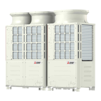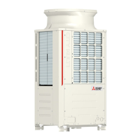
Do you have a question about the Mitsubishi Electric PUHY-P120THMU-A and is the answer not in the manual?
| Brand | Mitsubishi Electric |
|---|---|
| Model | PUHY-P120THMU-A |
| Category | Air Conditioner |
| Language | English |
Explains WARNING and CAUTION symbols, and provides safety guidelines for unit installation.
Covers electrical work safety, proper wiring, and precautions for refrigerant leaks and modifications.
Advises on handling unit components, securing covers, and safety during refrigerant charging and system operation.
Details requirements for R410A piping, storage, and system preparation to prevent contamination.
Specifies tools for R410A, refrigerant charging methods, and vacuum pump usage.
Advises on safe installation locations, avoiding gas leak areas and unusual environments.
Covers measures for noise interference in hospitals and avoiding water exposure.
Emphasizes proper grounding, using specified wires, and installing earth leakage breakers.
Provides guidelines for safe handling, transport, and disposal of packing materials.
Details necessary tools, materials, and initial servicing steps.
Covers piping materials, storage, processing, brazing, and air tightness tests.
Explains refrigerant charging, leak remedies, and refrigerant characteristics.
Provides important notes regarding the use and contamination of refrigerating machine oil.
Summarizes system configuration, compatible indoor units, and capacity limits.
Specifies allowable cable types, maximum lengths, and wiring notes.
Details switch settings for various units and address settings for controllers.
Provides sample system connection diagrams for MA, M-NET, and combined controller setups.
Outlines restrictions on refrigerant pipe length and diameter for various system configurations.
Identifies key outdoor unit components and illustrates the refrigerant circuit.
Details the control box contents, circuit boards, and associated components.
Shows the transformer box and noise filter components within the outdoor unit.
Compares functionalities, specifications, and selection criteria for MA and ME remote controllers.
Guides on setting up groups and interlocks using ME and MA remote controllers.
Explains how to utilize the built-in temperature sensor on the remote controller.
Provides detailed electrical wiring diagrams for various outdoor unit models.
Presents the electrical wiring diagram for the transmission booster.
Illustrates the refrigerant flow paths for different outdoor unit models.
Details key components like compressors, sensors, valves, and their specifications.
Explains dipswitch functions and factory settings for outdoor unit control.
Covers control methods, startup sequences, and bypass operations.
Describes operation modes, emergency operation, and defrost control procedures.
Explains DEMAND control and refrigerant recovery procedures.
Lists essential checks and the method for performing a test run.
Details operating characteristics, symptoms of incorrect refrigerant, and adjustment procedures.
Provides formulas and examples for calculating refrigerant amounts to be added.
Lists normal operating symptoms and standard operation data for reference.
Comprehensive list of error codes and guidance for responding to remote controller displays.
Guides investigation of transmission wave shape/noise and sensor faults.
Troubleshooting for principal parts like sensors, valves, fans, and compressors.
Details troubleshooting for inverter-related issues, power breakers, and wiring.
Troubleshooting steps for refrigerant leaks and compressor replacement.
Explains how to read LED indicators and information displayed during initial settings.
Details time data storage functions and various data displays based on SW1 settings.
Provides tables for current data and setting data displayed via SW1 configurations.


