EasyManua.ls Logo

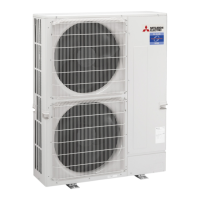
Mitsubishi Electric PUHZ-ZRP100VKA3 User Manual

Mitsubishi Electric PUHZ-ZRP100VKA3
119 pages
To Next Page IconTo Next Page
Page #1 background imageLoading...
Page #1 background image
SPLIT-TYPE, HEAT PUMP AIR CONDITIONERS
SERVICE MANUAL
R410A
Outdoor unit
[Model Name]
PUHZ-ZRP100VKA3
PUHZ-ZRP125VKA3
PUHZ-ZRP140VKA3
PUHZ-ZRP100YKA3
PUHZ-ZRP125YKA3
PUHZ-ZRP140YKA3
PUHZ-ZRP200YKA2
PUHZ-ZRP250YKA2
[Service Ref.]
PUHZ-ZRP100VKA3.UK
PUHZ-ZRP125VKA3.UK
PUHZ-ZRP140VKA3.UK
PUHZ-ZRP100YKA3.UK
PUHZ-ZRP125YKA3.UK
PUHZ-ZRP140YKA3.UK
PUHZ-ZRP200YKA2.UK
PUHZ-ZRP250YKA2.UK
PARTS CATALOG (OCB645)
CONTENTS
1. REFERENCE MANUAL ································· 2
2. SAFETY PRECAUTION ································· 2
3. FEATURES ····················································· 6
4. SPECIFICATIONS ·········································· 7
5. DATA ······························································· 9
6. OUTLINES AND DIMENSIONS ··················· 13
7. WIRING DIAGRAM ······································ 15
8. WIRING SPECIFICATIONS ·························· 18
9.
REFRIGERANT SYSTEM DIAGRAM
············· 23
10. TROUBLESHOOTING ·································· 26
11. FUNCTION SETTING ··································· 83
12.
MONITORING THE OPERATION DATA BY THE REMOTE CONTROLLER
···· 92
13. EASY MAINTENANCE FUNCTION ··········· 101
14. DISASSEMBLY PROCEDURE ··················· 104
Note:
•
This manual describes service
data of the outdoor units only.
No. OCH645
September 2016
Other manuals for Mitsubishi Electric PUHZ-ZRP100VKA3

Questions and Answers:

Mitsubishi Electric PUHZ-ZRP100VKA3 Specifications

General IconGeneral
ModelPUHZ-ZRP100VKA3
CategoryAir Conditioner
TypeOutdoor Unit
Cooling Capacity10.0 kW
Heating Capacity11.2 kW
Energy Efficiency Ratio (EER)3.21
Seasonal Energy Efficiency Ratio (SEER)6.10
RefrigerantR410A
Outdoor Unit Noise Level52 dB(A)
Power Supply380-415V, 50Hz
Indoor Unit Noise LevelNot applicable
Indoor Unit Dimensions (HxWxD)Not applicable
Indoor Unit WeightNot applicable

Summary

Reference Manual

Safety Precautions

Always Observe for Safety

General safety rules before accessing terminals.

Cautions Related to New Refrigerant

Cautions for units utilizing refrigerant R410A.

Cautions for Service

Cautions for performing service and handling refrigerant.

Additional Refrigerant Charge

Guidelines for additional refrigerant charging.

Features

Specifications

Data

Outlines and Dimensions

Wiring Diagram

Wiring Specifications

Field Electrical Wiring (Power Wiring Specifications)

Power wiring specifications for various models.

Separate Indoor Unit/Outdoor Unit Power Supplies

Connection patterns for separate indoor/outdoor unit power supplies.

Indoor – Outdoor Connecting Cable

Specifications for indoor-outdoor connecting cables.

Refrigerant System Diagram

Troubleshooting

Check Point Under Test Run

Points to check before and during test runs.

Self-Diagnosis and Remote Controller Check

Procedures for self-diagnosis and remote controller checks.

Self-Diagnosis Action Table

Action table for self-diagnosis errors detected on power-on.

Troubleshooting of Problems

Troubleshooting common problems and their solutions.

Function Setting

Unit Function Setting by the Remote Controller

Setting unit functions using the remote controller.

Function Selection of Remote Controller

Overview of function selection screen and buttons on remote controller.

Monitoring the Operation Data by the Remote Controller

Monitor Operation Data

Procedure to monitor operation data via remote controller.

Request Code List

List of request codes and their corresponding data.

Easy Maintenance Function

Smooth Maintenance

Using smooth maintenance for checking data and improving inspections.

Disassembly Procedure

Removing Panels and Fan Motor

Procedures for removing service panels, top panel, and fan motor.

Removing Electrical Parts Box and Components

Procedures for removing electrical parts box, its components, and related wiring.

Removing Thermistors

Procedures for removing various thermistor sensors.

Removing Valves, LEV, and High Pressure Switch

Procedures for removing 4-way valve, LEV, and high pressure switch.

Removing Compressor and Power Receiver

Procedures for removing the compressor and power receiver.

Removing Reactors (DCL/ACL)

Procedures for removing reactors (DCL for V model, ACL for Y model).

Related product manuals