23
Unit: mm (inch)
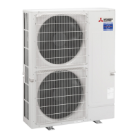
Refrigerant LIQUID pipe
connection [9.52 (3/8)
Stop valve
(with service port)
Strainer
#100
Power
receiver
Linear
expansion valve B
Linear expansion valve A
Strainer
#100
High pressure
switch 63H
Thermistor TH4
(Discharge)
Thermistor TH33
(Comp. surface)
Compressor
Strainer
#50
Strainer
#100
Strainer
#100
Strainer
#100
4-way valve
Muffler
Charge plug
(Low pressure)
Charge plug
(High pressure)
Ball valve
Refrigerant GAS pipe
connection [15.88 (5/8)
Refrigerant flow in cooling
Refrigerant flow in heating
Heat exchanger
Thermistor TH6
(2-phase pipe)
Thermistor TH7
(Ambient)
Thermistor TH3
(Liquid)
Distributor
PUHZ-ZRP100VKA3.UK PUHZ-ZRP125VKA3.UK
PUHZ-ZRP100YKA3.UK PUHZ-ZRP125YKA3.UK
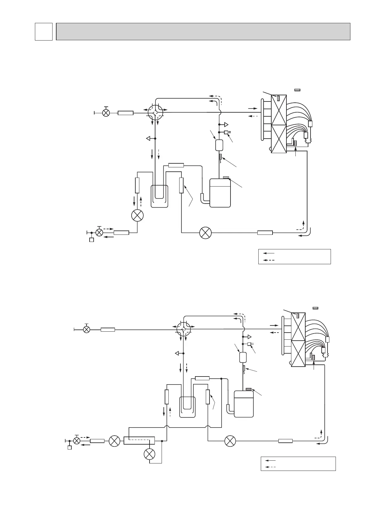
PUHZ-ZRP140VKA3.UK
PUHZ-ZRP140YKA3.UK
Refrigerant LIQUID
pipe connection
[9.52(3/8)
Stop valve
(with service port)
Strainer
#100
Power
receiver
Linear
Heat interchange
circuit
expansion
valve B
Linear
expansion
valve C
Linear expansion valve A
Strainer
#100
High pressure
switch 63H
Thermistor TH4
(Discharge)
Thermistor TH33
(Comp. surface)
Compressor
Strainer #50
Strainer
#100
Strainer
#100
Strainer
#100
4-way valve
Muffler
Charge plug
(Low pressure)
Charge plug
(High pressure)
Ball valve
Refrigerant GAS pipe
connection [15.88(5/8)
Refrigerant flow in cooling
Refrigerant flow in heating
Heat exchanger
Thermistor TH6
(2-phase pipe)
Thermistor TH7
(Ambient)
Thermistor TH3
(Liquid)
Distributor
9 REFRIGERANT SYSTEM DIAGRAM
Unit: mm (inch)
 Loading...