SERVICE MANUAL
CONTENTS
1. REFERENCE MANUAL ····························· 2
2. SAFETY PRECAUTION ·····························2
3. FEATURES ············································· 6
4. SPECIFICATIONS ···································· 7
5. DATA······················································ 9
6. OUTLINES AND DIMENSIONS ················· 13
7. WIRING DIAGRAM ································· 16
8. WIRING SPECIFICATIONS ······················ 19
9.
REFRIGERANT SYSTEM DIAGRAM
············ 23
10. TROUBLESHOOTING ····························· 26
11. EASY MAINTENANCE FUNCTION ············ 79
12. FUNCTION SETTING ······························ 81
13.
MONITORING THE OPERATION DATA BY THE REMOTE CONTROLLER
·· 83
14. DISASSEMBLY PROCEDURE ·················· 92
15. REMOTE CONTROLLER ························105
No. OCH750
REVISED EDITION-A
R410A
November 2020
Note:
• This manual describes ser-
vice data of the outdoor units
only.
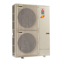
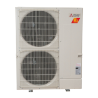
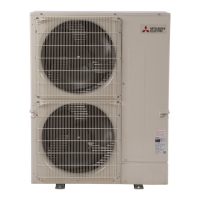
PUZ-HA24NHA1
PUZ-HA30NKA
PUZ-HA36NKA
PUZ-HA42NKA1
PARTS CATALOG (OCB750)
[Model Name]
[Service Ref.]
PUZ-HA24NHA1
PUZ-HA30NKA
PUZ-HA36NKA
PUZ-HA42NKA1
SPLIT-TYPE, HEAT PUMP AIR CONDITIONERS
PUZ-HA30NKA
PUZ-HA36NKA
PUZ-HA42NKA1
PUZ-HA24NHA1
Revision:
•
Some descriptions have
been modified
in REVISED
EDITION-A
.
OCH750 is void.