EasyManua.ls Logo

Mitsubishi Electric SEZ Series User Manual

Mitsubishi Electric SEZ Series
52 pages
To Next Page IconTo Next Page
Page #1 background imageLoading...
Page #1 background image

Questions and Answers:

Mitsubishi Electric SEZ Series Specifications

General IconGeneral
RefrigerantR410A
SeriesSEZ
Cooling CapacityVaries by model (e.g., 2.5kW to 14kW)
Heating CapacityVaries by model (e.g., 2.8kW to 16kW)
Power Supply220-240V, 50Hz
Energy Efficiency Ratio (EER)Varies by model (e.g., 3.5 to 4.5)
Coefficient of Performance (COP)Varies by model (e.g., 3.8 to 4.8)
Indoor Unit Noise LevelVaries by model
Outdoor Unit Noise LevelVaries by model
Outdoor Unit Dimensions (HxWxD)Varies by model
Indoor Unit WeightVaries by model
Outdoor Unit WeightVaries by model

Summary

Safety Precautions and Handling

General Safety and New Refrigerant Cautions

Covers warnings for R32 refrigerant, general safety, and new refrigerant handling procedures.

Service and Refrigerant Handling

Details cautions for service operations and additional refrigerant charging procedures.

R32 Refrigerant Unit Cautions

Specific safety guidelines for units utilizing R32 refrigerant, including work area and checks.

Service Tools for Refrigerant Handling

Lists and specifies the essential service tools required for R32/R410A refrigerant operations.

Part Names and Functions

Indoor Unit Components Overview

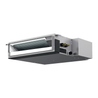
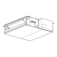
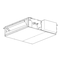
Identifies key components of the indoor unit for the SEZ-M series.

Wired Remote Controller Display and Functions

Explains the display modes and functions of the wired remote controller (PAR-41MAA).

Remote Controller Interface and Button Operations

Details the controller interface, button functions, and basic operation.

Remote Controller Menu Structure and Navigation

Outlines the navigation and options available within the remote controller menu system.

Maintenance and Service Menus via Remote

Describes the maintenance and service functions accessible via the remote controller.

Operation and Energy Saving Settings

Details settings for operation modes, timers, and energy-saving functions.

System Settings and Information Display

Explains settings for clock, display, initialization, and error information.

Wireless Remote Controller Functions

Illustrates the display and functions of the wireless remote controller.

Unit Specifications

SEZ-M25DA(L)2 Unit Specifications

Technical specifications for the SEZ-M25DA(L)2 indoor unit, including power, airflow, and sound.

SEZ-M35DA(L)2 Unit Specifications

Technical specifications for the SEZ-M35DA(L)2 indoor unit, including power, airflow, and sound.

SEZ-M50DA(L)2 Unit Specifications

Technical specifications for the SEZ-M50DA(L)2 indoor unit, including power, airflow, and sound.

SEZ-M60DA(L)2 Unit Specifications

Technical specifications for the SEZ-M60DA(L)2 indoor unit, including power, airflow, and sound.

SEZ-M71DA(L)2 Unit Specifications

Technical specifications for the SEZ-M71DA(L)2 indoor unit, including power, airflow, and sound.

Noise Criterion Curves by Static Pressure

Presents noise level data across different octave bands for various static pressures.

Indoor Fan Performance and Airflow Curves

Details the performance curves of the indoor fan for different models and static pressures.

Outlines and Dimensions

Unit Dimensions and Connection Point Layout

Provides overall dimensions and locations for piping and electrical connections.

Maintenance Access Space Requirements

Illustrates required clearances for maintenance and installation access.

Wiring Diagram

Indoor Control Box Wiring Schematic

Shows the internal wiring schematic of the control box and component connections.

DIP Switch Settings for Configuration

Details the configuration settings for DIP switches on the indoor controller board.

Refrigerant System Diagram

Refrigerant Flow Paths and Components

Illustrates the refrigerant flow within the system during cooling and heating operations.

Troubleshooting Guide

General Troubleshooting Cautions

Important safety and procedural notes to follow before and during troubleshooting.

Troubleshooting by Check Code Summary

Provides a summary of check codes, their symptoms, and initial service actions.

Self-Diagnosis with Remote Controller

Step-by-step guide to perform self-diagnosis using the remote controller.

Indoor Unit Error Code Detection and Symptoms

Lists error codes, their corresponding symptoms, and remarks for indoor unit issues.

Indoor Controller LED Status Indicators

Explains the meaning of LED indicators on the indoor controller board.

Detailed Self-Diagnosis Action Table

Detailed table linking error codes to abnormal points, causes, and countermeasures.

Troubleshooting Inferior Phenomena

Addresses troubleshooting based on abnormal phenomena like LED blinking or power issues.

Indoor Controller Board Test Points Diagram

Diagrams and descriptions of test points on the indoor controller board for diagnostics.

Trouble Criteria for Key Components

Defines normal/abnormal resistance and voltage criteria for key components.

DC Fan Motor and Controller Troubleshooting

Procedure for diagnosing and resolving issues related to the DC fan motor and its circuit.

Disassembly Procedures

Control Box and Intake Thermistor Removal

Instructions for removing the control box cover and the intake air thermistor.

Drainpan and Filter Removal

Procedure for removing the air filter, bottom plate, and drainpan.

Condenser/Evaporator Thermistor Removal

Steps for removing the heat exchanger cover and replacing thermistors.

Fan and Fan Motor Disassembly

Detailed instructions for disassembling the fan casing and removing the fan motor.

Bearing and Heat Exchanger Removal

Procedure for removing bearings (specific models) and the heat exchanger.

Related product manuals