EasyManua.ls Logo

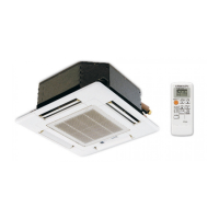
Mitsubishi Electric SLZ-KA09NA User Manual

Mitsubishi Electric SLZ-KA09NA
32 pages
To Next Page IconTo Next Page
Page #1 background imageLoading...
Page #1 background image
TECHNICAL & SERVICE MANUAL
SPLIT-TYPE, HEAT PUMP AIR CONDITIONERS
CONTENTS
1. PART NAMES AND FUNCTIONS
.......
2
2. SPECIFICATIONS
...............................
5
3. OUTLINES AND DIMENSIONS
...........
7
4. WIRING DIAGRAM
..............................
9
5.
REFRIGERANT SYSTEM DIAGRAM
.....
10
6. TROUBLESHOOTING
.......................
11
7. SPECIAL FUNCTION
........................
23
8. 4-WAY AIR FLOW SYSTEM
..............
26
9. DISASSEMBLY PROCEDURE
..........
28
November 2010
No. OCH487
REMOTE CONTROLLER
(Option)
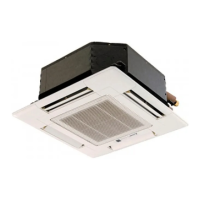
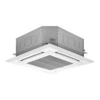
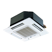
Indoor unit
[Model names] [Service Ref.]
SLZ-KA09NA SLZ-KA09NA.TH
SLZ-KA12NA SLZ-KA12NA.TH
SLZ-KA15NA SLZ-KA15NA.TH
INDOOR UNIT
Model name
indication
ON/OFF
TEMP.
Note:
• This manual describes only
service data of the indoor
units.
• RoHS compliant products
have <G> mark on the spec
name plate.
• For servicing RoHS compli-
ant products, refer to the
RoHS Parts List.
PARTS CATALOG (OCB487)
9700058
Questions and Answers:

Mitsubishi Electric SLZ-KA09NA Specifications

General IconGeneral
BrandMitsubishi Electric
ModelSLZ-KA09NA
CategoryAir Conditioner
LanguageEnglish

Summary

PART NAMES AND FUNCTIONS

Indoor Unit Components Identification

Details the parts of the indoor unit like air outlet, filter, and intake.

Optional Remote Controller Types

Shows images and types of optional remote controllers available.

WIRED REMOTE CONTROLLER

Wired Remote Controller Operation and Controls

Explains button functions and operational modes of the wired remote.

Wired Remote Controller Display Functions and Indicators

Describes the display section, indicators, and various display messages.

Wired Remote Controller Physical Dimensions

Provides the physical dimensions and mounting overview of the wired remote controller.

SPECIFICATIONS

Unit Operating Range Specifications

Details operating ranges for voltage, temperature, and humidity.

Airflow Speed and Coverage Specifications

Lists airflow speed and coverage for different models and functions.

NOISE CRITERION CURVES

OUTLINES AND DIMENSIONS

WIRING DIAGRAM

REFRIGERANT SYSTEM DIAGRAM

TROUBLESHOOTING

General Troubleshooting Cautions and Safety

Advises on safety precautions before and during troubleshooting procedures.

Performing Unit Self-Check Diagnostics

Guides on how to initiate and interpret the unit's self-diagnostic mode.

Self-Diagnosis Action Table for Error Codes

Details error codes, causes, and countermeasures for system malfunctions.

TEST POINT DIAGRAM

Indoor Power Board Test Point Diagram

Shows test points on the indoor power board for diagnostic measurements.

Indoor Controller Board Test Point Diagram

Illustrates test points on the indoor controller board for analysis and testing.

TROUBLE CRITERION OF MAIN PARTS

Thermistor Characteristic Graphs and Data

Displays resistance vs. temperature curves and characteristic data for thermistors.

FUNCTIONS OF DIP SWITCH AND JUMPER WIRE

SPECIAL FUNCTION

Rotation Function and Back-up Operation Modes

Describes how main/sub units alternate operation for load balancing and backup.

2nd Stage Cut-in Function for Capacity Control

Explains how a second unit activates for high-demand conditions and its cut-out logic.

Back-up Heating Functionality and Connection

Details the back-up heater activation based on temperature difference and connection methods.

4-WAY AIR FLOW SYSTEM

Fresh Air Intake Location and Ducting Requirements

Specifies installation locations for fresh air intake duct holes as required.

Fresh Air Intake Amount and Static Pressure Characteristics

Provides characteristic curves for fresh air intake amount versus static pressure.

Operation with Duct Fan (Booster Fan)

Explains how to connect and operate the unit in conjunction with an external duct fan.

Fixing and Adjusting Horizontal Vanes

Details the procedure to fix horizontal vanes for specific airflow directions.

DISASSEMBLY PROCEDURE

Disassembly: Air Intake Grille and Fan Guard Removal

Step-by-step guide to remove the air intake grille and fan guard.

Disassembly: Panel and Control Box Cover Removal

Instructions for removing various panels and the control box cover.

Disassembly: Removing Thermistors and Drain Pan

Covers removal of thermistors, drain pan, and piping covers.

Disassembly: Fan Motor and Drain Pump Removal

Details the process for removing the fan motor, drain pump, and sensor.

Disassembly: Heat Exchanger Removal Procedure

Step-by-step guide to safely remove the heat exchanger assembly.

Related product manuals