S
Sarah CamposSep 1, 2025
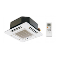
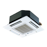
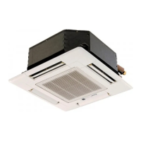
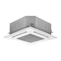
What does “ ” mean on my Mitsubishi Electric SLZ-KA50VA remote controller?
- MMichelle LeeSep 1, 2025
During central control, “ ” appears in the Mitsubishi Electric remote controller display and air conditioner operation cannot be started or stopped using the remote controller.