Do you have a question about the Mitsubishi Heavy Industries FDU224KXZE1 and is the answer not in the manual?
| Type | Split System |
|---|---|
| Cooling Capacity (kW) | 22.4 |
| Heating Capacity (kW) | 25.0 |
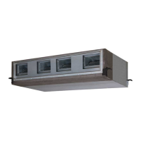
| Indoor Unit Model | FDU224KXZE1 |
| Outdoor Unit Model | FDC224KXZE1 |
| Refrigerant | R410A |
Specifies the KXZ series of VRF inverter multi-system air-conditioners.
Detailed specifications for duct-connected, high static pressure type indoor units.
Detailed specifications for outdoor air processing units.
Exterior dimensions and installation layout for indoor units.
Exterior dimensions and installation layout for outdoor air processing units.
Installation details and guidelines for the RC-EX1A wired remote control.
Installation details and guidelines for the RC-E5 wired remote control.
Electrical wiring diagrams for duct-connected, high static pressure type indoor units.
Electrical wiring diagrams for outdoor air processing units.
Fan performance curves for duct-connected, high static pressure type indoor units.
Fan performance curves for outdoor air processing units.
Noise level data for duct-connected, high static pressure type indoor units.
Noise level data for outdoor air processing units.
Capacity tables for duct-connected, high static pressure type indoor units.
Installation manual and guidelines for indoor units.
Detailed instructions for duct installation for indoor units.
Instructions for drain pipe installation and connection.
Guidelines for selecting the optimal installation location for indoor units.
Steps and considerations for preparing the installation site and unit.
Instructions for installing and connecting refrigerant pipes.
Explanation of control mode switching using DIP switches on the PCB.
Procedure for setting indoor and outdoor unit addresses for system communication.
Wiring, functions, and setup of remote control systems.
Details on setting functions using DIP switches on the PCB.
Overview of functions configurable via remote control buttons.
Settings accessible by the administrator for system configuration and maintenance.
Advanced functions and operational settings configurable via the remote control.
Essential safety guidelines and warnings for remote control installation and use.
Step-by-step guide for installing the remote control unit.
Configuration steps for master/slave setup with multiple remote controls.
Overview of operation control features for optional remote controls.
Detailed description of the wired remote control's functions and operation.
Explains operation control functions available via the wired remote control.
Procedure for resetting the remote control or system microcomputers.
How the system handles power failures and resumes operation.
Fundamental steps and methods for system troubleshooting using a PC.
A list of inspection displays and their corresponding classifications and pages.
Troubleshooting steps and countermeasures for specific error codes.
Details on how functional items operate during cooling and heating modes.
Specific control procedures for dehumidifying operation.
Explanation of various timer settings and their operation.
Fan control settings when heating thermostat is OFF.
Fan control settings when cooling thermostat is OFF.
Control functions for automatic louvre swing operation.
How the thermostat operates in cooling and heating modes.
Explanation of the filter sign indicator and its reset procedure.
Control logic to prevent compressor damage during frequent start/stop cycles.
Operation logic for the drain pump and its settings.
Control logic for the drain motor based on float switch and timer.
Procedures for operating checks and drain pump testing.
Measures to prevent frost formation during cooling or dehumidifying operations.
Troubleshooting and countermeasures for anomalous fan motor operation.
Adjustments for optimal airflow in rooms with high ceilings.
Detection of thermistor faults and related system responses.
Controls for external input/output signals connected via CnT or CnTA.
Outputs from the indoor control PCB for external monitoring.
Input signals for remote operation via CnT-6 or CnTA connectors.
Controls for permitting or prohibiting unit operation based on external input.
How to select cooling or heating modes using external input signals.
Adjusting temperature detection for improved heating comfort.
Compensating for deviations in return air temperature detection.
Operation mode for maximum performance for a limited time.
Operation mode for reduced power consumption.
Control function to warm up the indoor temperature before a set start time.
Mode to maintain moderate room temperature during long periods of non-use.
Automatic adjustment of set temperature based on outdoor air temperature.
Operation of the fan for air circulation.
Operation judgment process executed periodically.
Automatic adjustment of fan speed for faster temperature attainment.
Alarm indication for indoor unit overload conditions.
Function to reduce power consumption by restricting maximum capacity.
Fundamental steps and methods for system troubleshooting using a PC.
A list of inspection displays and their corresponding classifications and pages.
Troubleshooting steps and countermeasures for specific error codes.
Steps for replacing the control PCB, including switch settings.
Steps for replacing the power PCB, noting differences by model.
Steps for replacing the fan motor control PCB.
Installation and operation of the wireless kit for remote control.
Methods for installing the wireless receiver on a ceiling or wall.
Installation instructions for the wireless remote control holder.
Procedures to avoid mixed communication issues with wireless remote controls.
Identification and description of the sections and buttons on the RCH-E3 remote control.
Guidelines for selecting wire types and sizes for remote control wiring.
Step-by-step procedures for installing the remote control.
Details on wiring the remote control and cable length considerations.
How to configure various functions using PCB switches and remote control buttons.
Instructions on setting functions using remote control buttons.
