-
108
-
'14 • KX-T-222
(2) Power PCB
SAFETY PRECAUTIONS
WARNING
CAUTION
WARNING
CAUTION
PSC012D035
● Read the "SAFETY PRECAUTIONS" carefully first of all and then strictly follow it during the replacement in order to protect yourself.
● The precautionary items mentioned below are distinguished into two levels, WARNING and CAUTION.
Both mentions the important items to protect your health and safety so strictly follow them by any means.
Wrong installation would cause serious consequences such as injuries or death.
Wrong installation might cause serious consequences depending on circumstances.
● After completing the replacement, do commissioning to confirm there are no abnormalities.
● Replacement should be performed by the specialist.
If you replace the PCB by yourself, it may lead to serious trouble such as electric shock or fire.
● Replace the PCB correctly according to these instructions.
Improper replacement may cause electric shock or fire.
● Shut off the power before electrical wiring work. Start the work after elapsing 1 minutes or more from power off.
Replacement during the applying the current would cause the electric shock, unit failure or improper running.
It would cause the damage of connected equipment such as fan motor,etc.
● Fasten the wiring to the terminal securely, and hold the cable securely so as not to apply unexpected stress on the terminal.
Loose connections or hold could result in abnormal heat generation or fire.
● Check the connection of wiring to PCB correctly before turning on the power, after replacement.
Defectiveness of replacement may cause electric shock or fire.
● In connecting connector onto the PCB, connect not to deform the PCB. It may cause breakage or malfunction.
● Insert connector securely, and hook stopper. It may cause fire or improper running.
● Bundle the cables together so as not to be pinched or be tensioned. It may cause malfunction or electric shock for disconnection
or deformation.
(1) Replace the PCB
1. Unscrew terminal(Arrow A) of the "E1, E2" wiring(yellow/green) that is connected to PCB.
2. Replace the PCB only after all the wirings connected to the connector are removed.
3. Fix the board such that it will not pinch any of the wires.
4. Reconnect the wirings to the PCB. Wiring connector color should match with the color of connector of the PCB.
5. Screw back the terminal(Arrow A) of the "E1, E2" wiring, that was removed in 1.
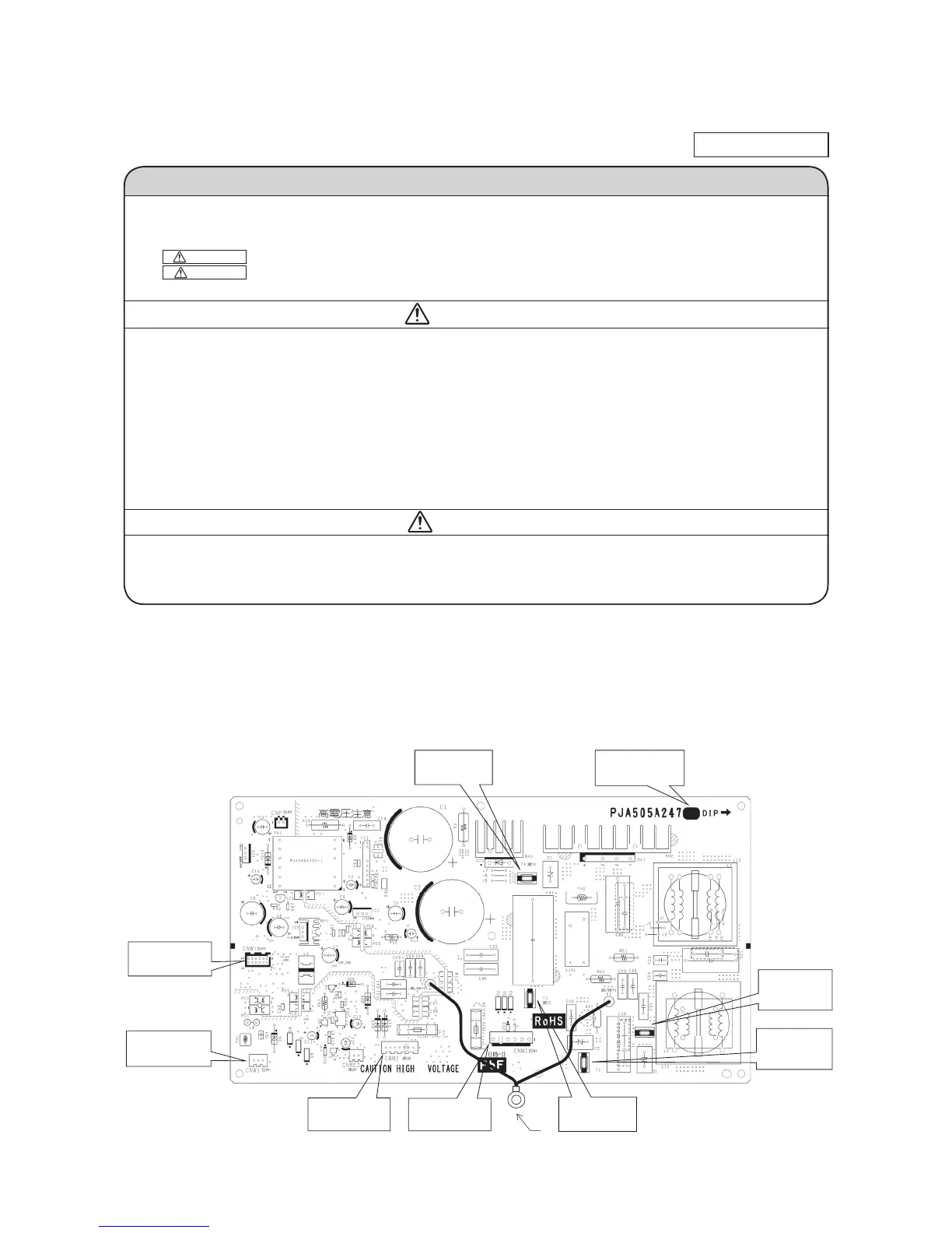
(2) Power PCB
Parts mounting are different by the kind of PCB.
(a) Models : FDU224KXZE1, 280KXZE1
FDU1800FKXZE1, 2400FKXZE1
CNW3 (White)
Terminal block
CNM1 (White)
Fan Motor1
CNW1 (White)
Control PCB
T1 (Red)
Terminal block
CNM2 (Black)
Fan Motor2
T4 (Yellow)
Reactor
T3 (Yellow)
Reactor
T2 (White)
Terminal block
Part number
PJA505A247□□
A
 Loading...