L-
1
c
11.
TROUBLESHOOTING
'
7
':3::
MELSEC-A
11.2
Bldirectlonrl Mode
Error
Codes
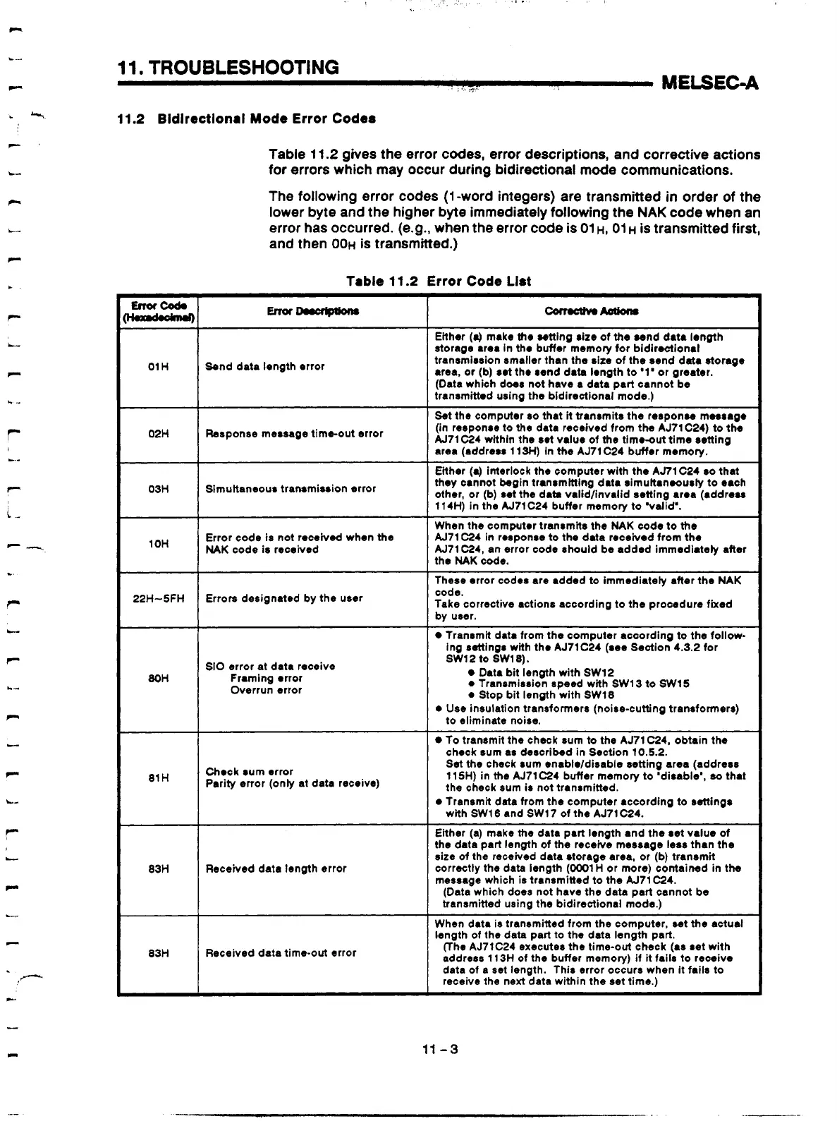
Table
1
1.2
gives the error codes, error descriptions, and corrective actions
for errors which may occur during bidirectional mode communications.
The following error codes
(1
-word integers) are transmitted
in
order of the
lower byte and the higher byte immediately following the
NAK
code when an
error has occurred. (e.g., when the error code is
01
H,
01
H
is transmitted first,
and then
001.1
is transmitted.)
Trble
11.2
Error
Code List
I
I
Either
(4
make the setting size of the sond data length
storaae area in tho buffer memorv for bidiroctional
01 H
Send data Iongth error
transmission smaller than the sit; of the send data storage
area,
or
(b) sot tho send data 10119th to '1' or greater.
(Oata which does not have a data part cannot be
transmittod using the bidirectional mode.)
02H
I
Response message time-out error
Set the computer
so
that
it
transmits the responw messago
(in response to
the
data received from the
AJ7l
C24) to the
A171C24 within the set value of the timoout time retting
area (address 11W) in the AJ71C24 buffer memory.
03H
Simultaneous transmission error
Either
(a)
interlock the computer with the AJ71 C24
so
that
they cannot begin transmltting data simultanoously to each
other,
or
(b) set the data validlinvalid setting area (address
114H) in the AJ71C24 buffer memory to 'valid'.
I
I
I
When the computer transmits the
NAK
code to the
a
-I
I
A171 C24 in rosponse to tho data received from the Error code is not receivd when the
1
un
NAK
code is received
A171 -4, an error code should be added immediately after
the
NAK
code.
These error codes are added to immediately after the NAK
I1
22H-5FH Errors designated by the user
code.
Take corrective actions according to the procedure fixed
by user.
I I
Transmit data from the computer accordina to the follow-
80H
SI0
error at data receive
Framing orror
Overrun error
I
sw12 to SW18).
ing settings with tho AJ71C24 (see Section4.3.2 for
Data bit length with SW12
0
Transmission speed with SWl3 to SW15
0
Stop bit lenath with SW18
0
use
insu~ition traisformers (noire-cutting transformers)
To transmit the check sum to the AJ71 C24, obtain the
to eliminate noise.
check sum as doscribed in Section 10.5.2.
81H
1
Chock sum error
Parity error (only at data receive)
Set
the check sum enabloldisable setting area (address
115H) in the AJ71 C24 buffer memory to 'disable',
so
that
the check sum is not transmitted.
b
Received data length error
0
Transmit data from the computer according to settings
Either (a) make the data part Iongth and the set value of
the
data part length of the receive message
bS8
than the
size of the received data storage area, or (b) transmit
correctly the data length (0001 H or more) contained in the
message which
is
transmitted to the A171 C24.
(Data which does not have the data part cannot be
transmitted using the bidirectional mode.)
with SW16 and SW17 of the AJ71C24.
When data is transmitted from the computer, set the actual
length of the data part
to
the data length part.
(The AJ71C24 executes the time-out check (as set with
address 11
3H
of
the buffer memory) if
it
fails to receive
data of a
set
length. This error occurs when it fails to
receive the next data within the set time.)
11
-3
Artisan Technology Group - Quality Instrumentation ... Guaranteed | (888) 88-SOURCE | www.artisantg.com
 Loading...


