4.
SETTINGS
AND
PROCEDURES BEFORE OPERATION
MELSEC-A
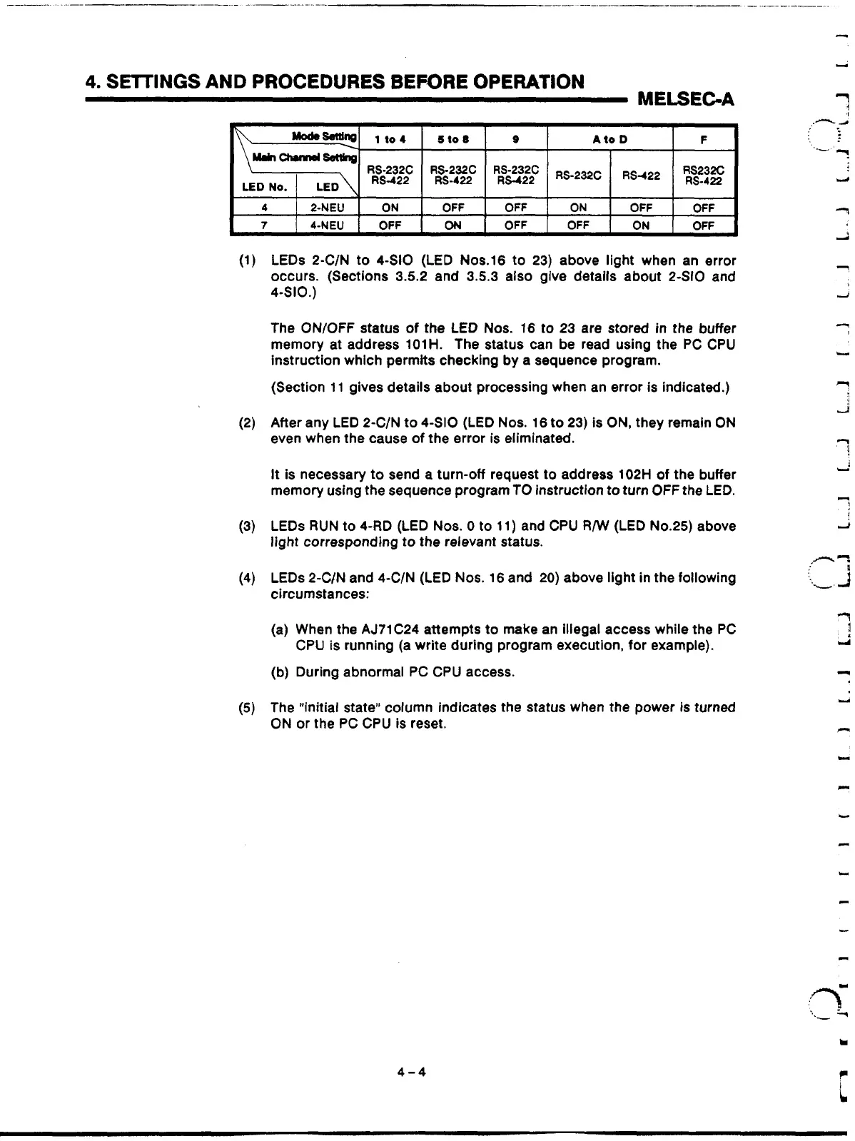
LEDs 2-C/N to 4-SI0 (LED Nos.16 to 23) above light when an error
occurs. (Sections 3.5.2 and 3.5.3 also give details about 2-SI0 and
4410.)
The ON/OFF status
of
the LED Nos.
16
to
23 are stored in the buffer
memory at address 101H. The status can be read using the PC CPU
instruction which permits checking by
a
sequence program.
(Section 11 gives details about processing when an error is indicated.)
After any LED 2-C/N to 4-SI0 (LED Nos. 16 to 23) is
ON,
they remain ON
even when the cause
of
the error
is
eliminated.
It
is necessary to send
a
turn-off request
to
address 102H
of
the buffer
memory using the sequence program TO instruction to
turn
OFF
the LED.
LEDs
RUN
to 4-RD (LED Nos.
0
to 11) and CPU
R/W
(LED
No.25)
above
light corresponding to the relevant status.
LEDs 2-C/N and 4-C/N (LED Nos. 16 and
20)
above light in the following
circumstances:
(a) When the AJ71C24 attempts to make an illegal access while
the
PC
CPU
is
running (a write during program execution, for example).
(b) During abnormal PC CPU access.
The "initial state" column indicates the status when the power is turned
ON
or the PC CPU is reset.
4-4
Artisan Technology Group - Quality Instrumentation ... Guaranteed | (888) 88-SOURCE | www.artisantg.com
 Loading...


