Chapter 2 Specifications
2–9
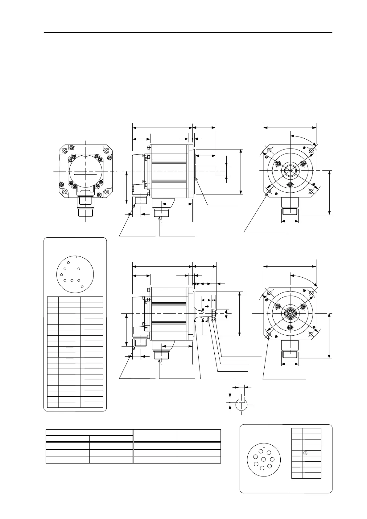
2-4 Outline dimension drawings
• HC52(B)S • HC52(B)T
• HC102(B)S • HC102(B)T
• HC152(B)S • HC152(B)T
• HC53(B)S • HC53(B)T
• HC103(B)S • HC103(B)T
• HC153(B)S • HC153(B)T
(Unit : mm)
S30457B
Oil seal
3
55
φ
110h7
φ
24h6
21.5
KL
81.5
12
L
44
CE05-2A22-23P
Power supply
connector
MS3102A22-14P
Detector
connector
50
□130
45°
4-φ9
Installation hole
Use a hexagon
socket head bolt.
φ
1
4
5
U nut M10×1.25
KL
81.5
5
0
-0.03
Cross section A-A
5
4.3
A
10
A
12 3
58
25
2818
12
φ
22
φ
110h7
Plain washer 10
Taper 1/10
φ
16.000
S30457B
L
44
CE05-2A22-23P
MS3102A22-14P
□130
45°
φ
1
4
5
41
111
φ
1
6
5
111
φ
1
6
5
21.5
Tightening torque
230~310 kgf・cm
41
Oil seal
Power supply
connector
Detector
connector
4-φ9
Installation hole
Use a hexagon
socket head bolt.
Servomotor type
2000r/min 3000r/min
L (Note 1) KL
HC52(B)□ HC53(B)□
125 (158) 51.5
HC102(B)□ HC103(B)□
150 (183) 76.5
HC152(B)□ HC153(B)□
175 (208) 101.5
Note 1. The dimensions given in parentheses are for when magnetic brakes
are provided.
Note 2. Use a friction coupling (Spun ring, etc.) to connect with the load.
Power supply connector
CE05-2A22-23P
D
Signal
Grounding
U
V
W
B
A
Pin
C
E
F
B1
G
B2
H
A
B
C
HF
E
D
G
B1 and B2 are the brake terminals.
(Only for motor with brakes.)
24VDC with no polarity.
Detector connector
MS3102A22-14P
E
J
K
H
N
L
RS
VV
S+5V
SD
J
Vx signal
BT
B
SD
E
A
Pin
F
D
C
G
H
RQ
K
RQ
L
M
SD
N
P
5G
R
T
U
P5
+5V
MDR
SVJ2 signal
BAT
MD
MR
MRR
SD
LG
The detector connector is common for all HC motors.
 Loading...


