Chapter 4 Characteristics
4–6
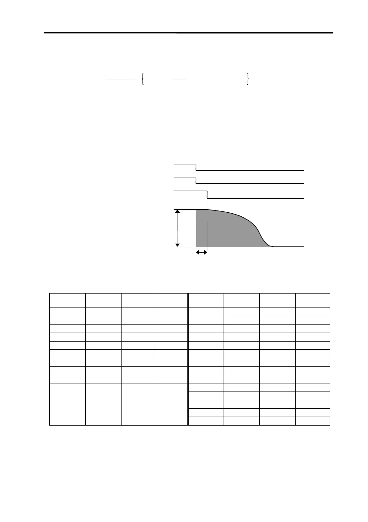
4-2-2 Coasting amount
The motor coasting amount when stopped by a dynamic brake can be approximated using the following
expression.
L
MAX
=
F
G0
× 10
3
60
× te + ( 1 +
J
L
J
M
) × 1.1 × (A × N
2
+ B)
L
MAX
: Machine coasting amount (mm)
F
G0
: Feedrate (Rapid traverse) (m/min)
N : Motor speed (speed at rapid traverse) (r/min)
J
M
: Motor inertia (kgf•cm•sec
2
)
J
L
: Motor shaft conversion load inertia (kgf•cm•sec
2
)
te : Brake drive relay delay time (Normally, 0.03sec) (sec)
A : Coefficient A (Refer to the table below)
B : Coefficient B (Refer to the table below)
Fig. 4-3 Dynamic brake braking diagram
Table 4-3 Coasting amount calculation coefficients
Motor type
J
M
(kgf•cm•sec
2
)
A B Motor type
J
M
(kgf•cm•sec
2
)
A B
HC52 (Note 1) 0.0067
9.57 × 10
−
9
7.09 × 10
−
3
HC53 (Note 1) 0.0067
9.49 × 10
−
9
6.37 × 10
−
3
HC52 (Note 2) 0.0067
3.59 × 10
−
9
4.79 × 10
−
3
HC53 (Note 2) 0.0067
2.56 × 10
−
9
6.09 × 10
−
3
HC102 0.014
2.47 × 10
−
9
5.69 × 10
−
3
HC103 0.014
1.95 × 10
−
9
6.98 × 10
−
3
HC152 0.02
1.76 × 10
−
9
5.89 × 10
−
3
HC153 0.02
1.28 × 10
−
9
9.13 × 10
−
3
HC202 0.043
15.20 × 10
−
9
9.56 × 10
−
3
HC203 0.043
9.77 × 10
−
9
60.90 × 10
−
3
HC352 0.084
8.74 × 10
−
9
13.02 × 10
−
3
HC353 0.084
4.97 × 10
−
9
24.23 × 10
−
3
HC452 0.123
2.80 × 10
−
9
19.26 × 10
−
3
HC453 0.123
2.44 × 10
−
9
32.87 × 10
−
3
HC702 0.163
13.30 × 10
−
9
6.82 × 10
−
3
HC703 0.163
1.58 × 10
−
9
36.65 × 10
−
3
HC902 0.208
2.07 × 10
−
9
26.52 × 10
−
3
HC103R 0.0015
1.24 × 10
−
9
1.22 × 10
−
3
HC153R 0.0019
0.95 × 10
−
9
1.20 × 10
−
3
HC203R 0.0023
0.59 × 10
−
9
1.61 × 10
−
3
HC353R 0.0085
1.18 × 10
−
9
5.19 × 10
−
3
HC503R 0.0122
0.96 × 10
−
9
5.64 × 10
−
3
Note 1. When using MDS-B-SVJ2
Note 2. When using MDS-B-V1/V2/V14/V24
OFF
ON
t
e
OFF
ON
OFF
ON
Emergency stop (EMG)
Dynamic brake actual operation
Coasting amount
Dynamic brake control
 Loading...


