Chapter 2 Specifications
2–13
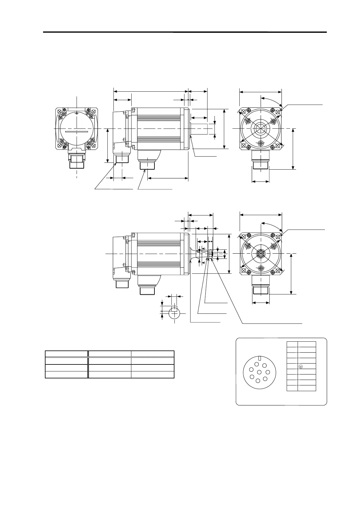
• HC103R(B)S • HC103R(B)T
• HC153R(B)S • HC153R(B)T
• HC203R(B)S • HC203R(B)T
(Unit : mm)
10
3
58
25
28
18
12
45
°
□
100
φ
1
3
5
φ1
1
5
A
A
10
φ
22
φ
95h7
M10
×
1.25 screw
U nut M10
×
1.25
Plain
washer 10
Taper 1/10
φ
16.000
Oil seal
S30457B
41
96
41
45
°
96
□
100
φ
1
3
5
φ
1
1
5
21.5
S30457B
Oil seal
L
44
10
3
45
CE05-2A22-23P
MS3102A22-14P
81.5
φ
95h7
φ
24h6
KL
5
0
-0.03
Cross-section
A-A
5
4.3
40
Tightening torque
230
~
310 kgf
・
cm
0
-0.03
Power supply
connector
Detector
connector
4-φ9
Installation hole
Use a hexagon
socket head bolt.
4-
φ
9
Installation hole
Use a hexagon
socket head bolt.
Servomotor type L (Note 1) KL
HC103R(B)
□
152 (189) 71
HC153R(B)
□
177 (214) 96
HC203R(B)
□
202 (239) 121
Note 1. The dimensions given in parentheses are for when magnetic brakes
are provided.
Note 2. Use a friction coupling (Spun ring, etc.) to connect with the load.
Note 3. Refer to section 2-9 for details on the detector connector.
CE05-2A22-23P
D
Signal
U
V
W
B
A
Pin
C
E
F
B1
G
B2
H
A
B
C
HF
E
D
G
Power supply connector
Grounding
B1 and B2 are the brake terminals.
(Only for motor with brakes.)
24VDC with no polarity.
 Loading...


