<3 phase>
<Figure 4.6.2>
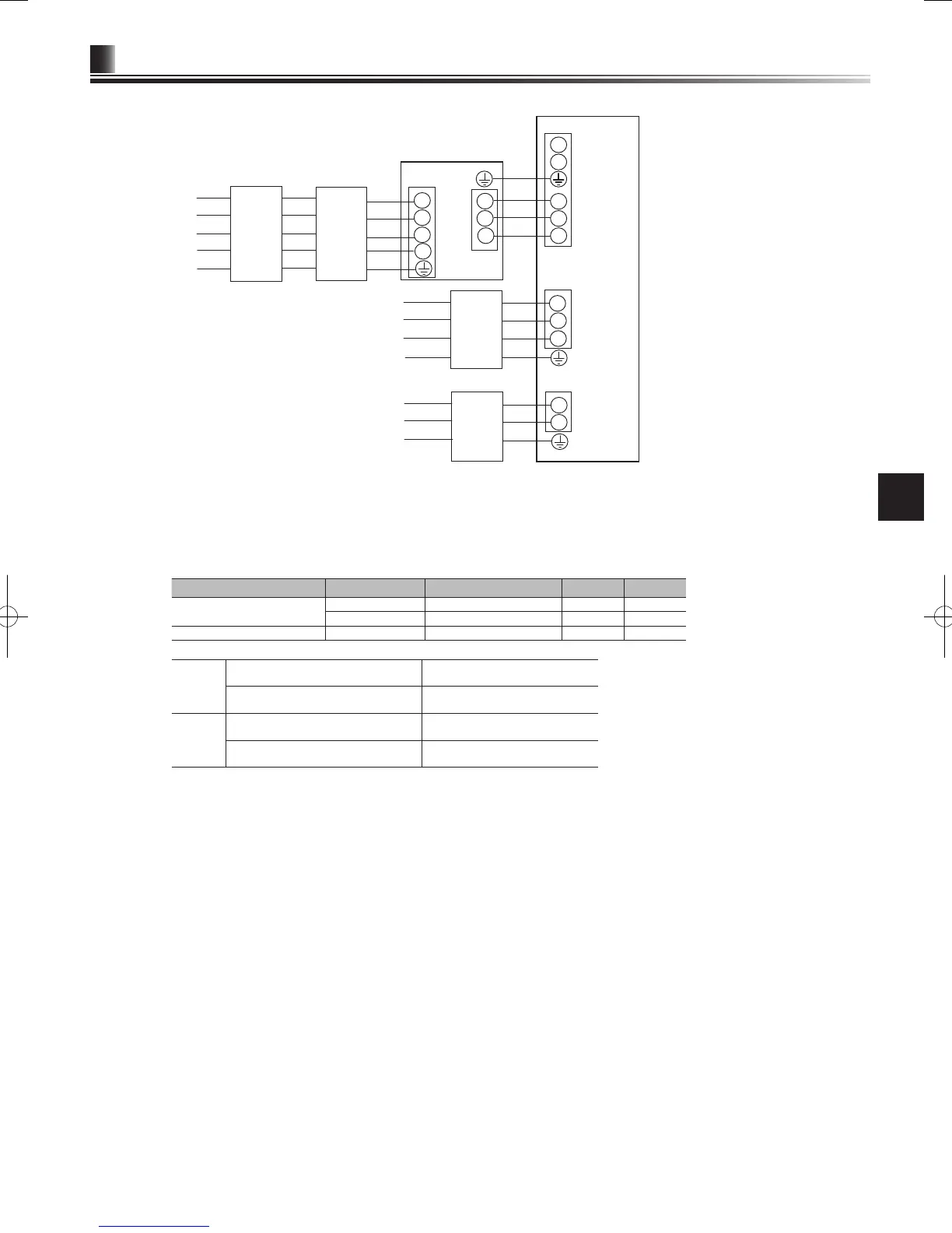
Electrical connections 3 phase
Description Power supply Capacity (Indoor unit Ref.) Breaker Wiring
Booster heater (Primary circuit)
3~ 400 V 50 Hz 9 kW 16 A *1 2.5 mm²
3~ 230 V 50 Hz 9 kW 32 A *1 6.0 mm²
Immersion heater (DHW tank) ~/N 230 V 50 Hz 3 kW 16 A *1 2.5 mm²
Wiring
Wiring No.
× size (mm²)
Cylinder unit - Outdoor unit *2 3 × 1.5 (polar)
Cylinder unit - Outdoor unit earth *2 1 × Min. 1.5
Circuit
rating
Cylinder unit - Outdoor unit S1 - S2 *3 230 V AC
Cylinder unit - Outdoor unit S2 - S3 *3 24 V DC
*1.
A breaker with at least 3.0 mm contact separation in each pole shall be provided. Use earth leakage breaker (NV).
The breaker shall be provided to ensure disconnection of all active phase conductors of the supply.
*2.
Max. 45 m
If 2.5 mm² used, Max. 50 m
If 2.5 mm² used and S3 separated, Max. 80 m
*3.
The values given in the table above are not always measured against the ground value.
N
ote: 1. Wiring size must comply with the applicable local and national codes.
2. Indoor unit/outdoor unit connecting cords shall not be lighter than polychloroprene sheathed exible cord. (Design 60245 IEC 57)
Indoor unit power supply cords shall not be lighter than polychloroprene sheathed exible cord. (Design 60227 IEC 53)
3.
Install an earth longer than other cables.
4. Please keep enough output capacity of power supply for each heater. The lack of the power supply capacity might cause
chattering.
*1
If the installed earth leakage circuit breaker does not have an over-current protection function, install a
breaker with that function along the same power line.
*2 Afx label A that is included with the manuals near each wiring diagram for cylinder unit and outdoor units

 Loading...