4.6 Electrical Connection
All electrical work should be carried out by a suitably qualied technician. Failure
to comply with this could lead to electrocution, re, and death. It will also invali-
date product warranty. All wiring should be according to national wiring regula-
tions.
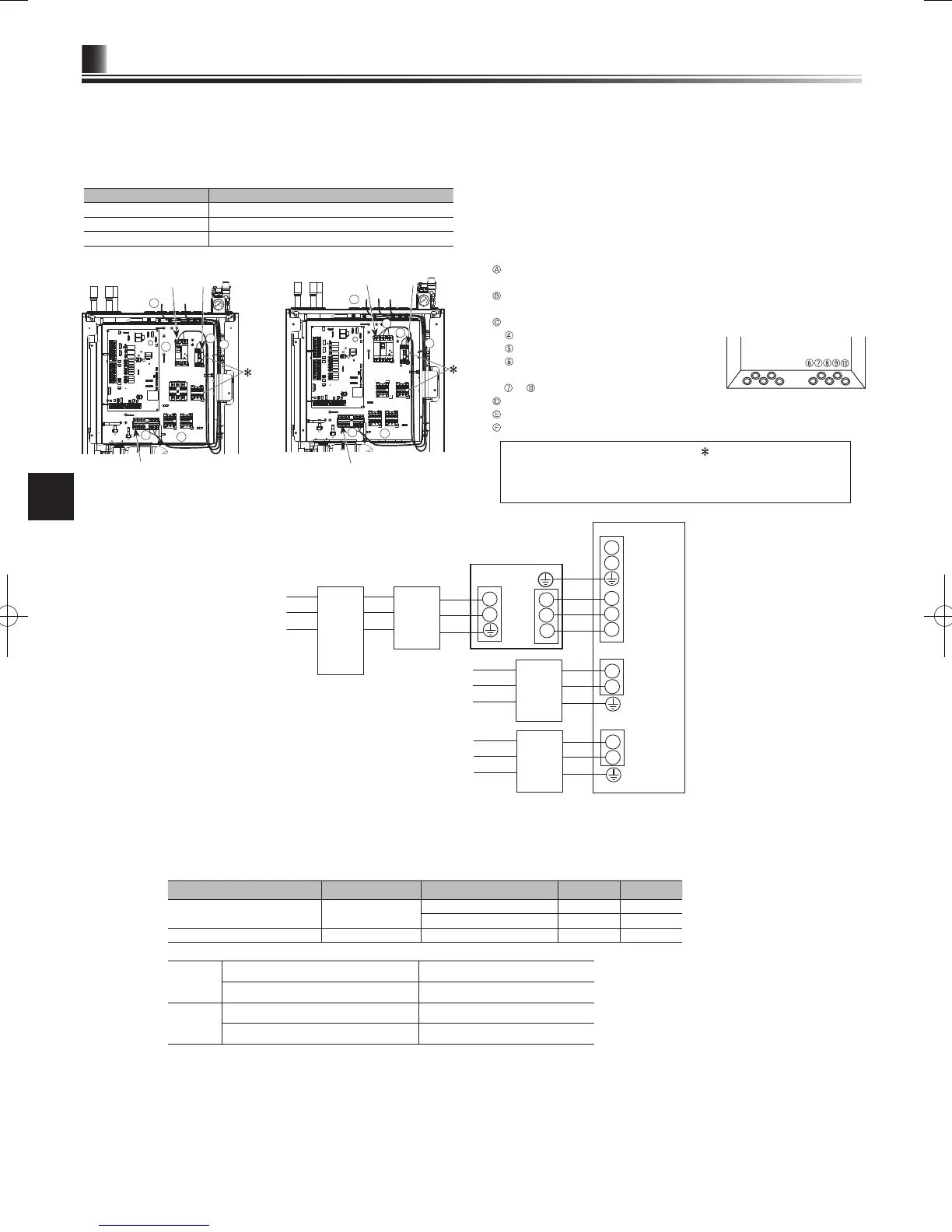
Option 1: Cylinder unit powered via outdoor unit
<1 phase>
<Figure 4.6.1>
Electrical connections 1 phase
Description Power supply Capacity Breaker Wiring
Booster heater (Primary circuit) ~/N 230 V 50 Hz 2 kW 16 A *1 2.5 mm²
6 kW 32 A *1 6.0 mm²
Immersion heater (DHW tank) ~/N 230 V 50 Hz 3 kW 16 A *1 2.5 mm²
Wiring
Wiring No.
× size (mm²)
Cylinder unit - Outdoor unit *2 3 × 1.5 (polar)
Cylinder unit - Outdoor unit earth *2 1 × Min. 1.5
Circuit
rating
Cylinder unit - Outdoor unit S1 - S2 *3 230 V AC
Cylinder unit - Outdoor unit S2 - S3 *3 24 V DC
*1.
A breaker with at least 3.0 mm contact separation in each pole shall be provided. Use earth leakage breaker (NV).
The breaker shall be provided to ensure disconnection of all active phase conductors of the supply.
*2.
Max. 45 m
If 2.5 mm² used, Max. 50 m
If 2.5 mm² used and S3 separated, Max. 80 m
*3.
The values given in the table above are not always measured against the ground value.
Note: 1. Wiring size must comply with the applicable local and national codes.
2. Indoor unit/outdoor unit connecting cords shall not be lighter than polychloroprene sheathed exible cord. (Design 60245 IEC 57)
Indoor unit power supply cords shall not be lighter than polychloroprene sheathed exible cord. (Design 60227 IEC 53)
3.
Install an earth longer than other cables.
4. Please keep enough output capacity of power supply for each heater. The lack of the power supply capacity might cause
chattering.
The cylinder unit can be powered in two ways.
1. Power cable is run from the outdoor unit to the cylinder unit.
2. Cylinder unit has independent power source
Connections should be made to the terminals indicated in the gures to the left
below depending on the phase.
Booster heater and immersion heater should be connected independently from
one another to dedicated power supplies.
Locally supplied wiring should be inserted through the inlets situated on the
top of the cylinder unit. (Refer to <Table 3.6>.)
Wiring should be fed down the right hand side of the control and electrical
box and clamped in place using clips provided.
The wires should be inserted individually through the cable inlets as below.
Outputs wire
Signal input wire
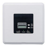
Wireless receiver (option) wire
(PAR-WR51R-E)
to Power line and indoor-outdoor wire
Connect the outdoor unit – cylinder unit connecting cable to TB1.
Connect the power cable for the booster heater to ECB1.
If immersion heater is present, connect the power cable to ECB2.
Breaker abbreviation Meaning
ECB1 Earth leakage circuit breaker for booster heater
ECB2 Earth leakage circuit breaker for immersion heater
TB1 Terminal block 1
<1 phase (with immersion heater)>
<3 phase (with immersion heater)>
• Avoid contact between wiring and parts
(
)
.
• Make sure that ECB1 and ECB2 are ON.
• On completion of wiring ensure main controller cable is connected to
the relay connector.
*1 If the installed earth leakage circuit breaker does not have an over-current protection function, install a breaker with that function along the same
power line.
*2 Afx label A that is included with the manuals near each wiring diagram for cylinder unit and outdoor units

 Loading...