Outdoor heat pump unit Water ow rate range [L/min]
Packaged PUHZ-W50 7.1 - 14.3
PUHZ-W85 10.0 - 25.8
PUHZ-HW112 14.4 - 27.7
PUHZ-HW140 17.9 - 27.7
Split PUHZ-RP35 7.1 - 11.8
PUHZ-RP50 7.1 - 17.2
PUHZ-RP60 8.6 - 20.1
PUHZ-(H)RP71 10.2 - 22.9
PUHZ-(H)RP100 14.4 - 27.7
PUHZ-(H)RP125 17.9 - 27.7
PUHZ-RP140 20.1 - 27.7
PUHZ-SW40 7.1 - 11.8
PUHZ-SW50 7.1 - 17.2
PUHZ-SW75 10.2 - 22.9
PUHZ-SW100 14.4 - 27.7
PUHZ-SW120 20.1 - 27.7
PUHZ-SHW80 10.2 - 22.9
PUHZ-SHW112 14.4 - 27.7
PUHZ-SHW140 17.9 - 27.7
<Table 4.3.1>
* If the water ow rate is less than 7.1 L/min, the ow switch will be activated.
If the water ow rate exceeds 27.7 L/min, the ow speed will be greater than 1.5 m/s,
which could erode the pipes.
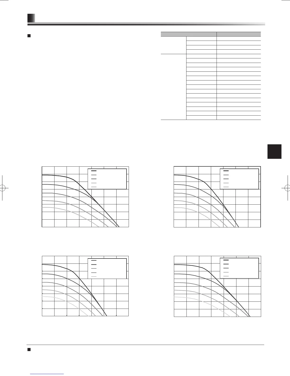
Water circulation pump characteristics
* For installation of EHPT20 series, set its pump speed with a pressure drop between the cylinder unit and the outdoor unit factored into the external static pressure.
External static pressure [kPa]
Flow rate [L/min]
<Figure 4.3.2>
EHST20 series
EHPT20 series (with PUHZ-W50)
<Figure 4.3.3>
Flow rate [L/min]
External static pressure [kPa]
Speed 5 (Default setting)
Speed 4
Speed 3
Speed 2
Speed 1
EHPT20 series (with PUHZ-W85)
EHPT20 series (with PUHZ-HW112/140)
External static pressure [kPa]
External static pressure [kPa]
Flow rate [L/min]
<Figure 4.3.4>
<Figure 4.3.5>
Flow rate [L/min]
Speed 5 (Default setting)
Speed 4
Speed 3
Speed 2
Speed 1
Speed 5 (Default setting)
Speed 4
Speed 3
Speed 2
Speed 1
Speed 5 (Default setting)
Speed 4
Speed 3
Speed 2
Speed 1
Water Circulation Pump Characteristics
Pump speed can be selected by main controller setting (see <Figure 4.3.2 to
4.3.5> ).
Adjust the pump speed setting so that the ow rate in the primary circuit is
appropriate for the outdoor unit installed (see Table 4.3.1). It may be necessary to
add an additional pump to the system depending on the length and lift of the
primary circuit.
<Second pump >
If a second pump is required for the installation please read the following
carefully.
If a second pump is used in the system it can be positioned in 2 ways.
The position of the pump inuences which terminal of the FTC4 the signal cable
should be wired to. If the additional pump(s) have current greater than 1A please
use appropriate relay. Pump signal cable can either be wired to TBO.1 1-2 or
CNP1 but not both.
Option 1 (Space heating only)
If the second pump is being used for the heating circuit only then the signal cable
should be wired to TBO.1 terminals 3 and 4 (OUT2). In this position the pump can
be run at a different speed to the cylinder unit’s in-built pump.
Option 2 (Primary circuit DHW and space heating)
If the second pump is being used in the primary circuit between the cylinder unit
and the outdoor unit (Package system ONLY) then the signal cable should be
wired to TBO.1 terminals 1 and 2 (OUT1). In this position the pump speed MUS
T
match the speed of the cylinder unit’s in-built pump.
N
ote: Refer to 5.2 Connecting inputs/outputs.
Immersion heater
When an immersion heater is tted, do NOT energise the heater until the DHW tank is full of water. Also do NOT energise any immersion heater if any sterilisation chemicals
remain in the DHW tank as this will cause premature failure of the heater.

 Loading...