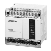
Do you have a question about the Mitsubishi FX1N-14MR-ES/UL and is the answer not in the manual?
| Series | FX1N |
|---|---|
| Input Points | 8 |
| Output Points | 6 |
| Output Type | Relay |
| Power Supply | 100 - 240VAC |
| Certification | UL, CE |
| Type | Programmable Logic Controller (PLC) |
| Communication Ports | RS-422 |
| Dimensions | 90mm x 90mm x 75mm |
| Program Memory | 8000 Steps |
Details global product specifications and model variations.
Explains the naming convention for FX1N series models.
Describes how to interpret product serial numbers.
Outlines system configuration and expansion options.
Displays system configuration diagrams.
Important notes and cautions for using expansion boards.
Tables detailing I/O points and power consumption.
Defines limits and rules for system expansion.
Information on EEPROM and capacitor data backup.
Details on program and parameter data backup.
Explains capacitor memory retention and recharge.
Wiring diagrams for AC powered main units.
Wiring diagrams for DC powered main units.
Terminal layouts for FX0N and FX2N-8E extension blocks.
Terminal layouts for FX2N extension blocks.
Features and components of the FX1N PLC.
Methods to control the PLC's RUN/STOP status.
Technical specifications like temperature, humidity, resistance.
Guidelines for mounting PLCs to prevent overheating.
Instructions for mounting units onto a DIN rail.
Information on direct mounting hole positions.
Procedures for connecting wires to screw terminals.
Guidance on installing expansion and special function units.
Explains installation of expansion boards with different modules.
Instructions for installing the FX1N-5DM display module.
How to install/remove extension modules.
General advice for safe and easy wiring.
Important warnings regarding signal and power cable routing.
Correct connection of AC and DC power supply terminals.
Details AC and DC power supply requirements and ratings.
Illustrative wiring diagrams for power supply connections.
Wiring example for AC power supply.
Wiring example for 24V DC power supply.
Wiring example for 12V DC power supply.
Information on service current supply capabilities.
Guidelines for proper equipment grounding.
Technical specifications for 24V DC inputs.
Illustrative wiring for PNP and NPN sensors.
How to connect input circuits for different units.
Guidelines for connecting diodes and LEDs in series.
Calculating resistors for parallel input configurations.
Specifications and connection for AC110V input blocks.
Wiring diagram for AC110V input extension blocks.
Cautions regarding programming with AC110V units.
Technical specs for relay and transistor outputs.
Typical wiring examples for relay outputs.
Test results on relay output load capacity and life.
Wiring examples for transistor outputs (source/sink).
Wiring diagram for source type transistor outputs.
Wiring diagram for sink type transistor outputs.
Information on output response times and dummy resistors.
Guidelines for safe load application with DC and AC loads.
Steps for initial PLC checks before operation.
Troubleshooting when the ERROR LED is on.
Lists common error types encountered with the PLC.
Recommendations for routine PLC maintenance.
Explains status flags and error indicators.
Details on PLC status registers like version and memory.
Register codes associated with different error types.
Specific error codes and their meanings.
A list of available PLC instructions and their functions.
Overview of device types like relays, timers, counters, and registers.


