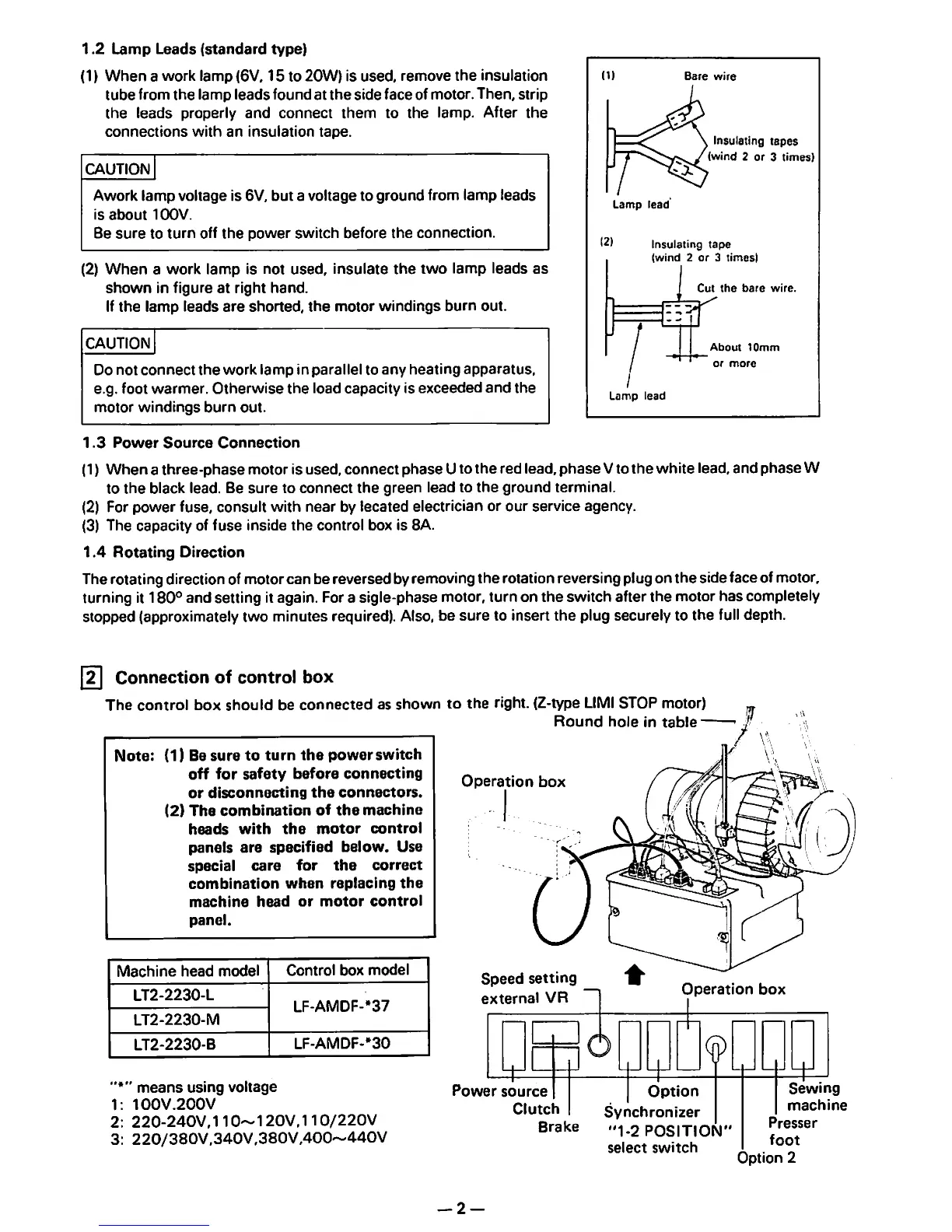
1.2
Lamp
Leads
(standard
type)
(1)
When
a
work
lamp
(6\/, 15 to
20W)
is
used,
remove
the
insulation
tube
from
the
lamp
leads
found at
the
sideface of motor. Then, strip
the
leads
properly
and
connect
them
to
the
lamp. After
the
connections
with
an
insulation
tape.
CAUTION
Awork
lamp
voltage is 6V, but a voltage to
ground
from
lamp
leads
is
about
10OV.
Be
sure
to
turn
off
the
power
switch
before
the
connection.
(2)
When
a work lamp is not used,
insulate
the
two
lamp leads
as
shown
in figure at right
hand.
If
the
lamp
leads
are
shorted,
the
motor
windings
burn
out.
CAUTION
Do
not
connect
the
work
lamp
in
parallel
to
any
heating
apparatus,
e.g. foot
warmer.
Otherwise
the
load capacity is
exceeded
and
the
motor
windings
burn
out.
Lamp
lead
Insulating
tapes
(wind
2 or 3
times)
12)
Insulating
tape
(wind
2
or
3
times)
/
Lamp
lead
Cut
the
bare
wire.
About
10mm
or
more
1.3
Power
Source
Connection
(1)
When
a
three-phase
motor is used, connect
phase
Uto the red lead,
phase
Vto
the
white lead, and
phase
W
to
the
black lead. Be
sure
to
connect
the
green
lead to
the
ground
terminal.
(2) For
power
fuse,
consult
with
near
by lecated electrician or our service agency.
(3)
The
capacity
of
fuse
inside
the
control
box is 8A.
1.4
Rotating
Direction
Therotating directionofmotorcan bereversed byremovingthe rotation reversing plugon the side face ofmotor,
turning it
180°
and setting it again. Fora sigle-phase motor, turn on the switch after the motor has completely
stopped (approximately two minutes required). Also, be
sure
to insert
the
plug securely to the full depth.
[n
Connection of control box
The
control
box
should
be
connected
as
shown
to
the
right. (Z-type LIMISTOP motor)
Round
hole
in
table-
Note:
(1) Be
sure
to
turn
the
power
switch
off
for
safety
before
connecting
or
disconnecting
the
connectors.
(2)
The
combination
of
the
machine
heads
with
the
motor
control
panels
are
specified
below.
Use
special
care
for
the
correct
combination
when
replacing
the
machine
head
or
motor
control
panel.
Operation
box
Machine
head
model
Control
box
model
LT2-2230-L
LF-AMDF-*37
LT2-2230-M
LT2-2230-B
LF-AMDF-'30
Speed
setting
external
VR
Operation
box
means
using
voltage
1;
100V.200V
2:
220-240V,110~120V,110/220V
3:
220/380V,340V,380V,400~440V
Power
source
Clutch
Brake
— 2 —
Option
Synchronizer
"1-2
POSITION"
select
switch
Sewing
machine
Presser
foot
Option
2
 Loading...