Do you have a question about the Mitsubishi PLK-E1008H and is the answer not in the manual?
Details the meaning and usage of various warning signs in the manual.
Specifies conditions for temperature, humidity, atmosphere, voltage, and noise.
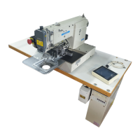
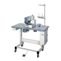
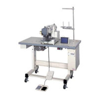
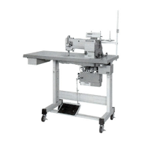
Comprehensive instructions for setting up the sewing machine and its components.
Steps for correct operation, including software loading and needle installation.
Guidance on safe sewing practices, teaching, and thread adjustments.
Procedure for aligning and adjusting the shuttle mechanism for optimal performance.
Ensuring correct alignment between the needle and the shuttle for proper stitch formation.
Setting the correct vertical position of the needle bar.
Details on sewing area, speed, stitch type, dimensions, and drive systems.
Information regarding the type and model of the main motor used.
Guidelines for preparing the sewing machine table for installation.
Instructions for preparing and assembling the steel stand.
Steps for installing the motor underneath the table.
Procedure for installing the control box underneath the table.
Guidance on connecting the teaching panel to the control box.
Detailed steps for attaching and connecting the power switch.
Procedure for connecting the foot switch to the control box.
Steps for assembling and fixing the oil pan onto the table.
Instructions for safely placing and securing the sewing machine head on the table.
Guidance on fitting the V-belt and adjusting its tension.
Detailed steps for connecting various electrical cables between components.
Procedure for attaching the belt cover mounting plate and cover.
Steps for assembling and securing the thread stand on the table top.
Instructions for connecting the air pressure regulator assembly and manifold.
Procedure for loading the system software onto the control box.
Steps for safely installing or replacing the machine needle.
Instructions and diagrams for threading the upper thread through the machine.
Step-by-step guide on how to wind thread onto the bobbin.
Instructions on how to properly remove the bobbin from the bobbin case.
Procedure for inserting the bobbin and threading it through the bobbin case.
How to use the emergency stop switch to halt operations safely.
Details on pattern input and operation peculiar to PLK-B1008H.
Using function code FN4 for pre-heating to ensure proper thread trimming.
Explanation of the three operation switches for thermal trimming.
Step-by-step instructions for performing the sewing operation safely.
Procedure for adjusting the bobbin thread tension using the adjusting screw.
How to adjust the upper thread tension based on the bobbin thread tension.
Detailed steps for adjusting the shuttle, including alignment and clearance.
Procedure to align the needle and shuttle correctly.
Detailed steps for adjusting the needle bar height.
Setting the correct clearance between the needle and shuttle blade.
Adjusting the clearance between the needle and needle guard of the driver.
Procedure to switch the machine into test mode for adjustments.
Explanation of how keys operate different functions in test mode.
Steps for adjusting the presser foot and its related components.
Adjusting the sensor associated with the presser foot cylinder.
Adjusting the thread puller for secure seam beginning.
Procedure for setting the thickness detector.
Adjusting the thread wiper for proper thread angle and contact.
Setting the angle and position of the upper thread heater.
Procedure to shift the mechanical home position in the X-axis direction.
Procedure to shift the mechanical home position in the Y-axis direction.
Checking and adjusting clearance for the X detector.
Setting the standard clearance for the Y-drive shaft.
Procedure to increase tension of the X timing belt.
Procedure to increase tension of the Y timing belt.
Identifies causes and remedies for frequent upper thread breakage.
Troubleshooting steps for when the upper thread is pulled from the needle.
Addresses issues with excessive thread tail length post-trimming.
Resolves problems where the trimming function does not operate.
Fixes issues caused by a deviated hook position.
Diagnoses and resolves common causes of skip stitching.
Addresses causes and solutions for loose stitch formation.
Troubleshoots why the machine fails to start when the switch is activated.
Diagnoses why the machine runs idle after the power switch is turned on.
Troubleshooting for when the work holder fails to operate correctly.
Resolves issues causing sewing patterns to be distorted.
Fixes for the work holder not stopping at the designated home position.
Addresses the work holder stopping at an incorrect original home position.
Diagram showing the interconnection of various wires and components.
Details on wiring connections between the power switch and the relay.
Technical drawing showing cut-out dimensions for the table.
Diagram and parts list for assembling the table and stand.
| Brand | Mitsubishi |
|---|---|
| Model | PLK-E1008H |
| Category | Sewing Machine |
| Language | English |