87
MECHANICAL STRUCTURE
5
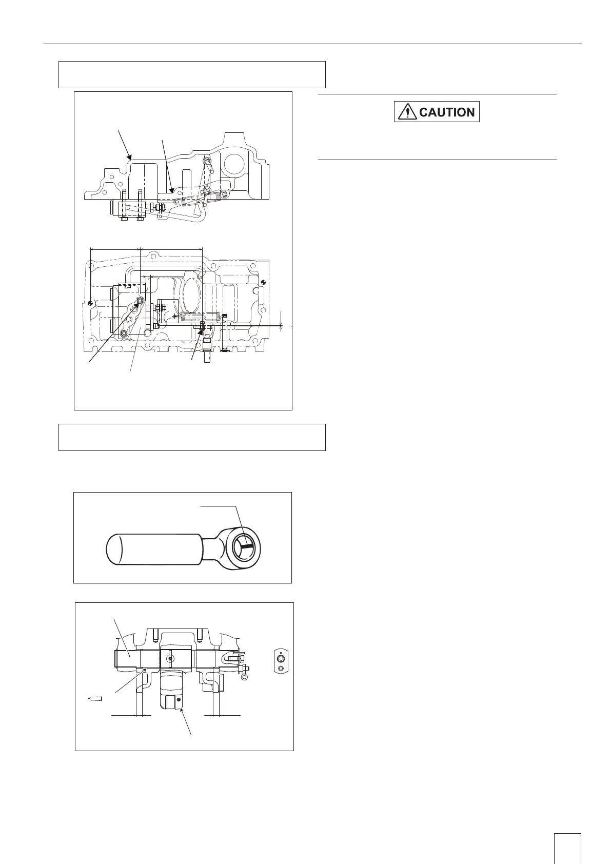
Installation of Hitch Control Valve
1. Set the clearance between the valve plate and valve
body to 10mm {0.394in}.
2. Make sure that the clearance "Z" between the
hydraulic housing and link assembly is within 0.5
to 2.0mm {0.02 to 0.079in}
3. Adjust the measurement of the center of valve
mounting bolt "X" and arm pin "Y" for level link to
137 ± 0.3mm {5.394 ± 0.012in} with W nut.
6
Assembly of Hydraulic Piston Rod
Wash the hydraulic equipment parts and assemble with
caution for entry of foreign matters.
Apply some oil to the O-ring, bush and seal for assembly.
1. Toward the slit of the bush on piston rod as
shown in the figure for mounting.
Reference) Apply some lubricant, MoS2-P, to
the bush inner diameter (pin oscillating part)
and oscillating part of the piston and piston
rod.
2. Toward the slit of the bush (left and right) for
lift shaft as shown in the figure for mounting.
1) Toward the slit of the bush as shown in the
figure for mounting.
2) The depth of press fit for bush shall be 13.5mm
{0.531in} on both lift and right.
Reference) Apply some lubricant, MoS2-P, to
the spline part of the shaft.
Make sure the O-ring is attached before
assembly.
P
C
P
O
137 0.3mm
{5.394
0.012in
}
10mm
{0.079
in
}
(109.5mm
{4.311
in
})
X
Y
Z
Hydraulic housing
Link assembly
Valve body
Valve plate
GZ3W31-025
GS7W4-058
Slit
7
Oil
13.5mm
{0.531in}
13.5mm
{0.531in}
A-A
GZ3W31-026A
Power arm
Lift shaft
Valve body
Valve plate
X
Y
(109.5mm{4.311in}) 137
㼼
0.3mm{5.394
㼼
0.012in}
10mm{0.079in}
Hydraulic housing
Link assembly
Z
5. Installation of Hitch Control Valve
6. Assembly of Hydraulic Piston Rod
 Loading...