86
MECHANICAL STRUCTURE
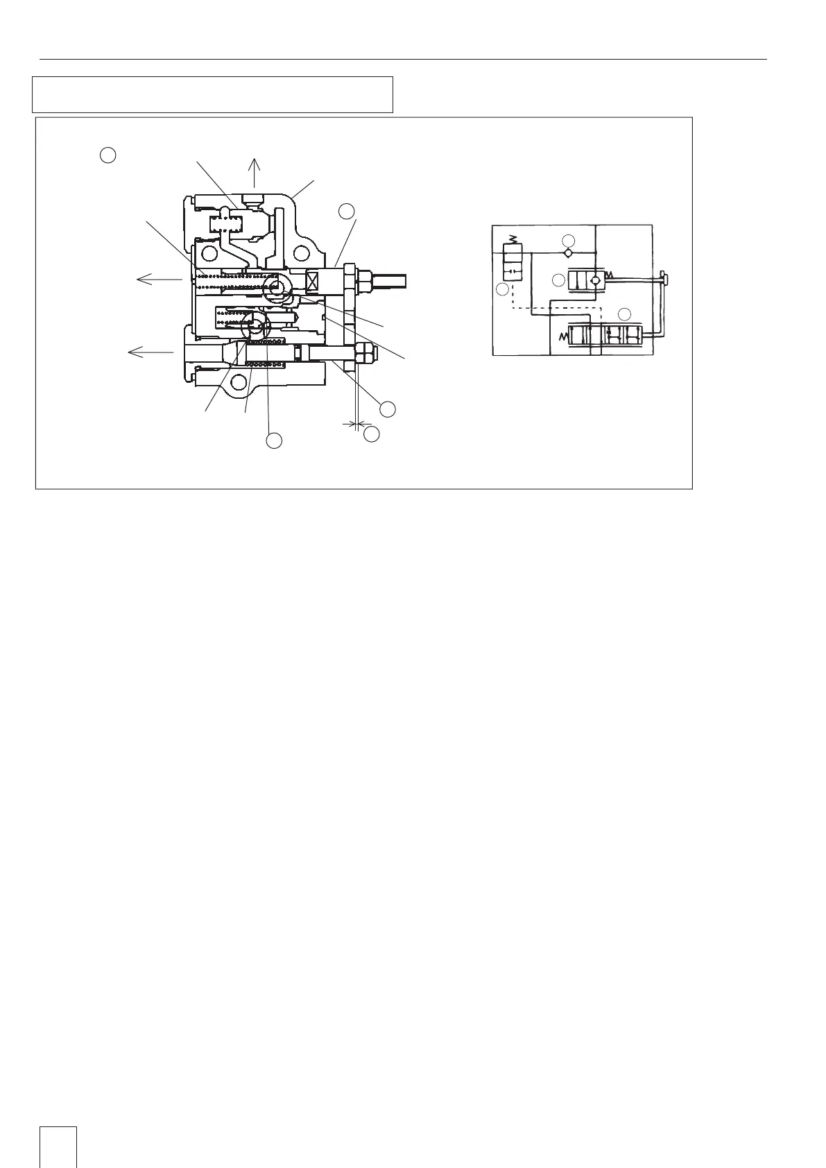
4 Assembly of Control Valve
1. Assembling Procedure
1) Line up all the parts disassembled and check the O-ring for scratches and wears. If any defects, change it.
2) Check the spool, movement of plunger, and sheet part for any
flaws
. If any flaws, smooth them with
oilstone.
3) Clean with cleaning fluid.
4) Make sure the assembling position and direction at assembly.
5) Apply some grease to O-ring when assembling it.
2. Adjusting Procedure
1) Remove the plug and the spring of unload valve.
2) The position, which changes the sound when moving the spool while blowing in the air from the
plug, is
the neutral position for the spool.
3) Set the clearance "T" with the nut connecting the plate and poppet within 0.3 to 0.6mm {0.012 to 0.024in}
in this position and lock.
Hydraulic
pressure signal
T
2
T1 P
C
T3
4
3
2
1
Neutral oil return
Valve body
Spool valve
Pump port
Poppet
Check valve
Poppet
spring
Cylinder port
Control Valve Sectional View
Cylinder return
Pilot oil return
Spool valve
spring
Unload valve
4
2
T 0.3 - 0.6mm
1
3
Sheet
GZ3W31-024A
4. Assembly of Control Valve
 Loading...