EasyManua.ls Logo

Mitsubishi MCFH-13NV User Manual

Mitsubishi MCFH-13NV
72 pages
To Next Page IconTo Next Page
Page #1 background imageLoading...
Page #1 background image
SERVICE MANUAL
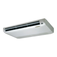
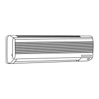
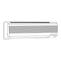
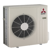
FLOOR AND CEILING TYPE AIR CONDITIONERS
CONTENTS
1. TECHNICAL CHANGES ····································3
2. PART NAMES AND FUNCTIONS······················3
3. SPECIFICATION·················································6
4. NOISE CRITERIA CURVES·······························7
5. OUTLINES AND DIMENSIONS ·························8
6. WIRING DIAGRAM ············································9
7. REFRIGERANT SYSTEM DIAGRAM··············14
8. PERFORMANCE CURVES······························16
9. MICROPROCESSOR CONTROL ····················32
10. SERVICE FUNCTIONS·····································41
11. TROUBLESHOOTING······································42
12. DISASSEMBLY INSTRUCTIONS·····················55
13. PARTS LIST······················································63
14. OPTIONAL PARTS···········································70
Wireless type
Models
MCFH-13NV-
(WH)
·MUCFH-13NV-
MCFH-18NV-
(WH)
·MUCFH-18NV-
MCFH-24NV-
(WH)
·MUCFH-24NV-
E3E3
E3E3
E4E4
No. OB267
(When installed on the ceiling)
(When installed on the floor)
This Service manual OB212 deals with MCFH-13/18/24/NV-E1,
MUCFH-13/18/24/NV-E1, MCFH-13/18/24/NV-E2 and MUCFH-
13/18/24/NV-E2 in OB196 REVISED EDITION A issued in
September in 1997.
Therefore, please refer to OB212, not to OB196 REVISED EDI-
TION A, for the above models.
W As for parts lists, all sub numbers series are included.
OB267--1.qxp 01.4.13 0:48 PM Page 1

Questions and Answers:

Mitsubishi MCFH-13NV Specifications

General IconGeneral
BrandMitsubishi
ModelMCFH-13NV
CategoryAir Conditioner
LanguageEnglish

Summary

PART NAMES AND FUNCTIONS

SPECIFICATION

Indoor Model Specifications

Provides technical specifications for indoor units.

Outdoor Model Specifications

Provides technical specifications for outdoor units.

WIRING DIAGRAM

Indoor Unit Wiring Diagrams

Electrical wiring diagrams for indoor units across models.

Outdoor Unit Wiring Diagrams

Electrical wiring diagrams for outdoor units across models.

REFRIGERANT SYSTEM DIAGRAM

Refrigerant Diagram - 13NV Models

Illustrates refrigerant flow for 13NV model indoor/outdoor units.

Refrigerant Diagram - 18NV Models

Illustrates refrigerant flow for 18NV model indoor/outdoor units.

Refrigerant Diagram - 24NV Models

Illustrates refrigerant flow for 24NV model indoor/outdoor units.

MAX. REFRIGERANT PIPING LENGTH & MAX. HEIGHT DIFFERENCE

ADDITIONAL REFRIGERANT CHARGE (R22 : g)

PERFORMANCE CURVES

PERFORMANCE DATA

MICROPROCESSOR CONTROL

"I FEEL CONTROL" Operation Modes

Details operation modes based on room temperature and user preference.

SERVICE FUNCTIONS

Compulsory Defrosting Mode

Enables forced defrosting for service purposes.

TROUBLESHOOTING

Troubleshooting Cautions

Important safety and handling precautions for troubleshooting.

Troubleshooting Flowchart

Step-by-step guide for diagnosing unit malfunctions.

Troubleshooting Check Table

Lists symptoms, indications, and check points for troubleshooting.

Trouble Criteria of Main Parts

Resistance values for diagnosing component failures.

Component Troubleshooting Checks

Detailed checks for specific components like motors and boards.

TEST POINT DIAGRAM AND VOLTAGE

DISASSEMBLY INSTRUCTIONS

PARTS LIST

Related product manuals