8 - 18
LOADING AND INSTALLATION8.
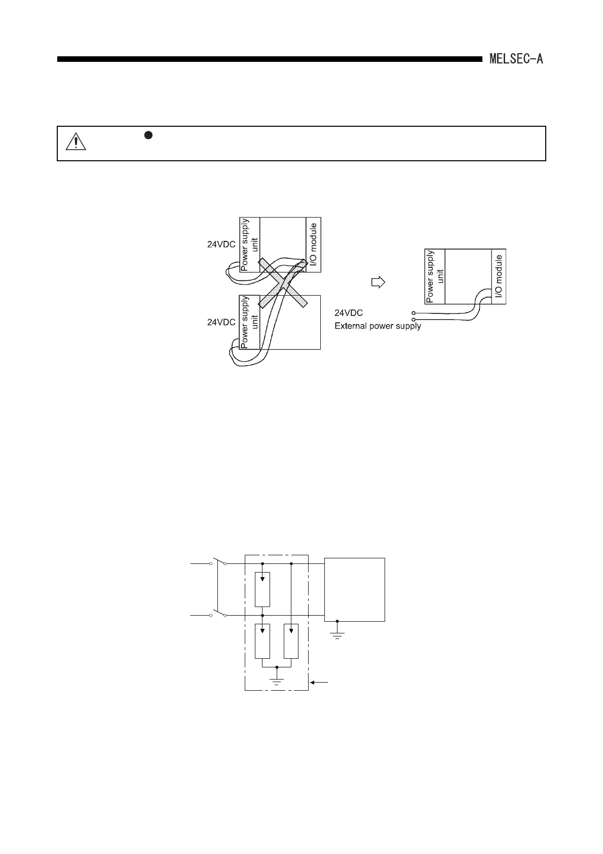
(f) Note on using the 24VDC output of the A1S62PN power supply module.
If the 24VDC output capacity is insufficient for one power supply module, supply
24VDC from the external 24VDC power supply as shown below:
(g) 100VAC, 200VAC and 24VDC wires should be twisted as dense as possible.
Connect the modules with a shortest distance.
Also, to reduce the voltage drop to the minimum, use thickest wires possible
(maximum 2mm
2
(0.0031in.
2
)).
(h) Do not bind 100VAC and 24VDC wires together with main circuit (high voltage
and large current) wires or I/O signal lines (including common line) nor place
them near each other. Provide 100mm (3.94inch) clearance between the wires if
possible.
(i) As measures against surge due to lightening, connect a surge absorber for
lightening as shown below.
CAUTION
Do not connect multiple power supply modules to one module in parallel.
The power supply modules may be heated, resulting in a fire or failure.
E1 E1
AC
Programmable
controller I/O
devices
surge absorber fo
lightening
E1
E2

 Loading...


