APP - 38
APPENDICES
*: Usable with AnN and AnA which are compatible with SFC.
For the AnN and AnA which are compatible with SFC, refer to the MELSAP-ll Programming Manual.
Table App2.2 Special Register List (Continue)
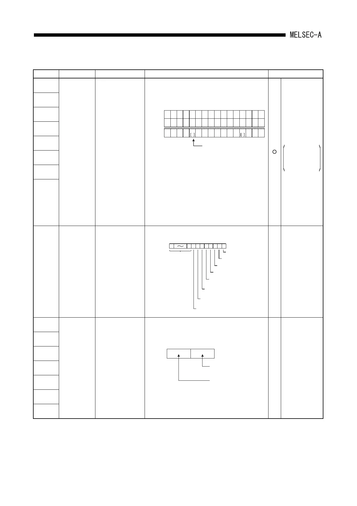
Number Name Description Details Applicable CPU
*1
D9100
Fuse blown
module
Bit pattern in units of
16 points of fuse blow
modules
• Output module numbers (in units of 16 points), of which
fuses have blown, are entered in bit pattern. (Preset
output unit numbers when parameter setting has been
performed.)
• Fuse blow check is executed also to the output module
of remote I/O station.
(If normal status is restored, clear is not performed.
Therefore, it is required to perform clear by user
program.)
(For the AnU, A2US(H) and QCPU-A (A mode))
• Data clear of D9100 to D9107 is executed by turning
off M9000 (fuse blown).
(For the CPU other than the AnU, A2US(H) and QCPU-
A (A mode))
• Data clear of D9100 to D9107 is executed by turning
off D9100 to D9107 (fuse blown).
Usable with all
types of CPUs
Only remote
I/O station
information
is valid for
A2C.
*1
D9101
*1
D9102
*1
D9103
*1
D9104
*1
D9105
*1
D9106
*1
D9107
*1
D9100
Fuse blow
module
Fuse blow module bit
pattern
• Stores the output module number of the fuses have
blown in the bit pattern.
—
Dedicated to
A0J2H.
*2
D9108
Step transfer
monitoring
timer setting
Timer setting value
and the F number at
time out
• Sets value for the step transfer monitoring timer and
the number of F which turns on when the monitoring
timer timed out.
(By turning on any of M9108 to M9114, the monitoring
timer starts. If the transfer condition following a step
which corresponds to the timer is not established within
set time, set annunciator (F) is tuned on.
—
Usable with AnN ,
AnA, AnU, A2AS,
AnA board,
QCPU-A (A
Mode), A2C,
A0J2H, AnS,
AnSH, A1FX and
A52G.
*2
D9109
*2
D9110
*2
D9111
*2
D9112
*2
D9113
*2
D9114
D9100
D9101
D9107
15 14 12 1113 1098 65432107
00 0000
1
(Y80)
00000000
0000
1
(Y1A)
00 00000000
00 000000000000
Indicates fuse blow.
D9100
D9101
D9107
15 14 12 1113 1098 65432107
00
1
(YC0)
00 00 00000000
1
(Y1F0)
0000 00 00000000
00 000000000000
1
Y7
BC
11
Y7
30
00
b15
D9100
b8 b7 b6 b5 b4 b3 b2 b1
0 is fixed.
Indicates the module
for setting switch 0.
Indicates the module
for setting switch 1.
Indicates the module
for setting switch 2.
Indicates the module
for setting switch 3.
Indicates the module for setting
switch 4 or the module for
extension base unit slot 0.
Indicates the module for setting
switch 5 or the module for
extension base unit slot 1.
Indicates the module for setting
switch 6 or the module for
extension base unit slot 2.
Indicates the module for setting switch 7 or
the module for extension base unit slot 3.
b0
b15 to b8 b7 to b0
Timer setting
(1 to 255 sec
in seconds)
F number setting
 Loading...


