11. OPTIONS AND AUXILIARY EQUIPMENT
11 - 46
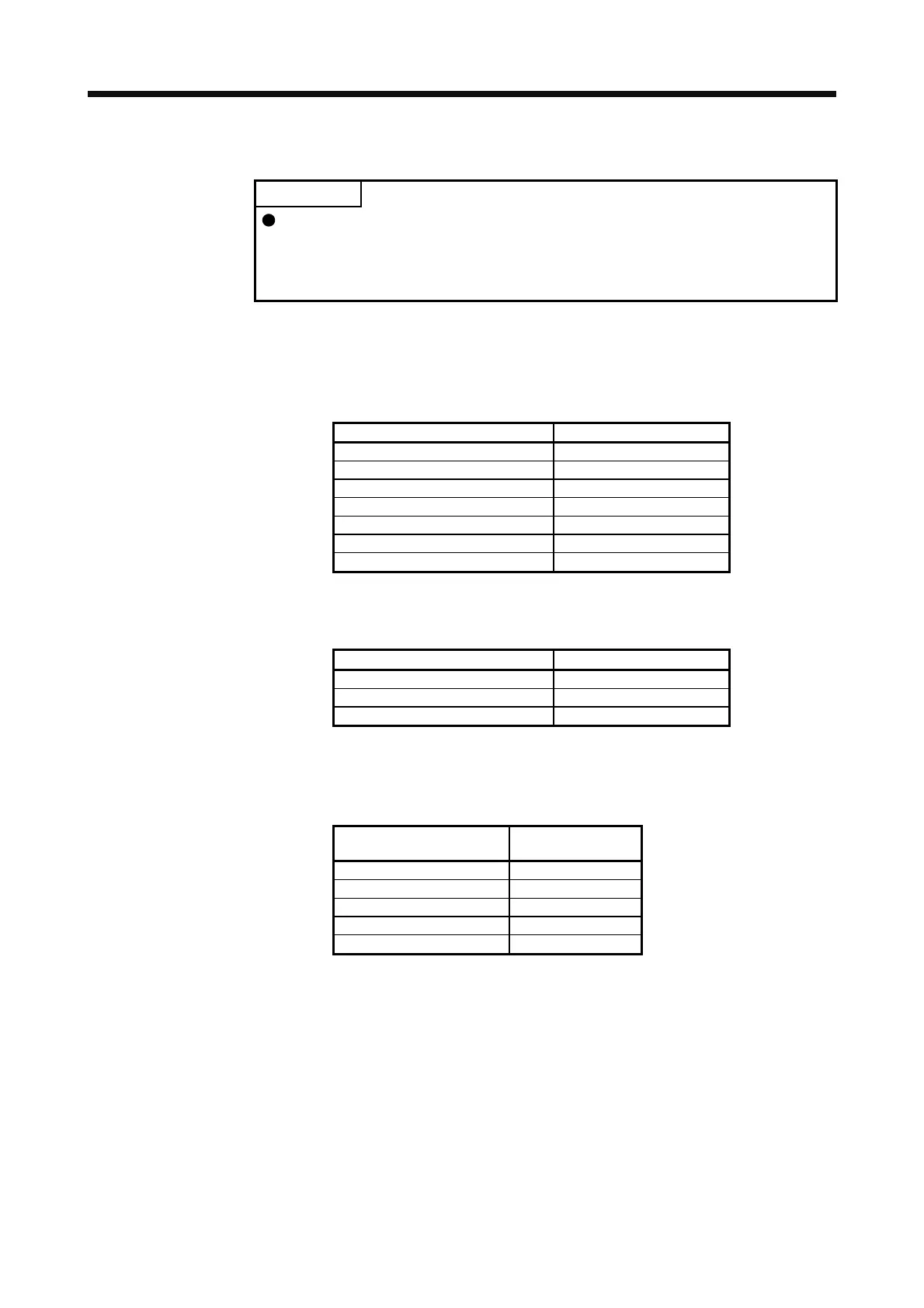
(4) Selection example of wires used for wiring
POINT
Selection condition of wire size is as follows.
Wire type: 600 V grade heat-resistant polyvinyl chloride insulated wire (HIV
wire)
Construction condition: Single wire set in midair
(a) Wire sizes
1) Across P to P4, N to N
The following table indicates the connection wire sizes of the DC power supply (P4, N- terminals)
between the FR-CV and servo amplifier.
Total of servo amplifier capacities [kW] Wire [mm
2
]
1 or less 2 (AWG 14)
2 3.5 (AWG 12)
5 5.5 (AWG 10)
7 8 (AWG 8)
11 14 (AWG 6)
15 22 (AWG 4)
22 50 (AWG 2)
The following table indicates the connection wire sizes of the DC power supply (P4, N- terminals)
between the FR-CV-H and servo amplifier.
Total of servo amplifier capacities [kW] Wire [mm
2
]
11 8 (AWG 8)
15 8 (AWG 8)
22 14 (AWG 6)
2) Grounding
For grounding, use the wire of the size equal to or greater than that indicated in the following
table, and make it as short as possible.
Power regeneration common
converter
Grounding wire size
[mm
2
]
FR-CV-7.5K to FR-CV-15K 8 (AWG 8)
FR-CV-22K/FR-CV-30K 22 (AWG 4)
FR-CV-37K/FR-CV-55K 38 (AWG 2)
FR-CV-H22K/FR-CV-H30K 8 (AWG 8)
FR-CV-H37K/FR-CV-H55K 14 (AWG 6)
 Loading...

