6
FUNCTIONS
6.11 Monitor Function
6.11.2 Local device monitor/test
6
- 52
1
Overview
2
Performance
Specification
3
Sequence Program
Configuration and
Execution Conditions
4
I/O Nunber Assignment
5
Memories and Files
Handled by CPU Module
6
Functions
7
Communication with
Intelligent Function
Module
8
Parameters
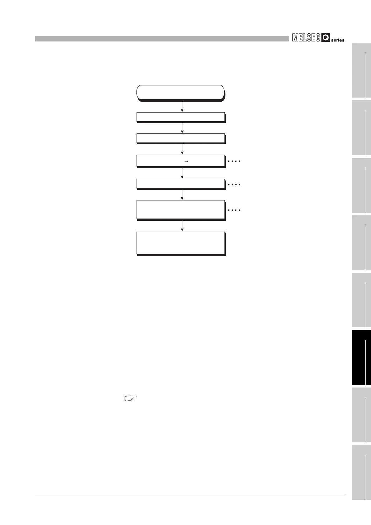
(2) Monitoring the Local Devices
Monitor local devices in the following steps:
(3) Precautions
(a) Local devices that can be monitored/tested by one GX Developer
It is only a single program that local devices can be monitored or tested by
operating from a single GX Developer. Local devices in multiple programs cannot
be monitored or tested by operating from a single GX Developer.
(b) Number of programs that can be monitored/tested
It is a maximum of 16 programs that local devices can be monitored or tested by
operating from multiple GX Developers connected to a RS-232 serial
communication module of the CPU module.
(c) Monitor of local devices in stand-by type program
When the local devices in the stand-by type program are monitored, the scan time
increases since the local device data are saved and restored.
( Section 9.13.1)
(d) Local device monitor of fixed scan execution type program
Local devices in a fix scan execution type program cannot be monitored or tested.
Diagram 6.35 Local device monitor procedure flowchart
Display the circuit in the circuit mode.
Change the mode to the monitor mode.
Select <Each program> tab.
Select "Monitor" to monitor
the local device.
The local device of the
displayed program is
monitored.
Connect the personral computer to
the CPU module.
Choose [Tools] [Options].
Setting of the local device
monitor
Change to the option
selection window by program
Display option window
 Loading...

