APPENDICES
Appendix 5 Device Point Assignment Sheet
App - 90
9
Device Explanation
10
CPU Module Processing
Time
11
Procedure for Writing
Program to CPU Module
AppendicesIndex
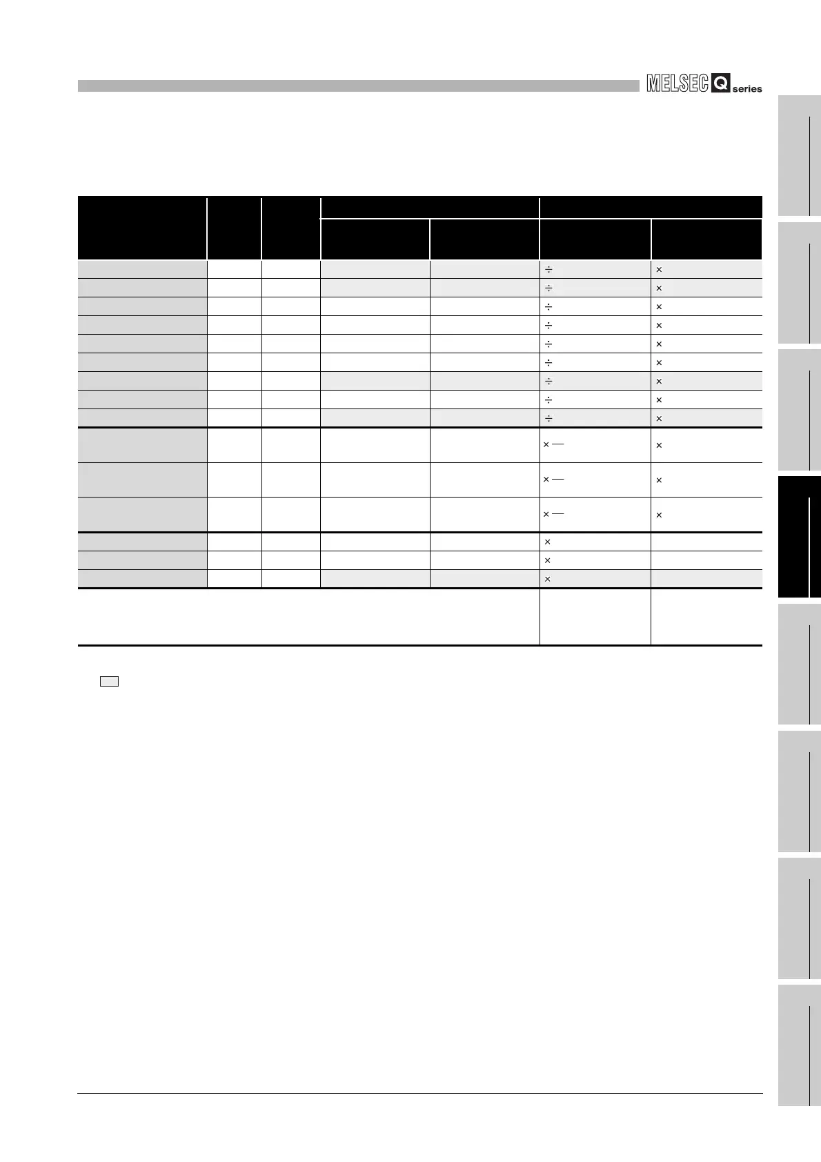
(2) For High Performance model QCPU, Process CPU, Redundant CPU
*1 : The hatched number of points is fixed. (Unchangeable)
*2 : The maximum number of points of one device is 32k points.
*3 : Enter the value that is obtained by multiplying (or dividing) the number of device points by the numeral indicated in the
capacity (word) field.
TableApp.46 Device Point Assignmene sheet (For High Performance model QCPU, Process CPU, Redundant CPU)
Device name Symbol
Numeric
notation
Number of device points
*1*2
Restriction check
Number of points Number
Capacity ( words)
*3
Number of bit
points
*2
Input relay X 16 8k (8192)points X0000 to 1FFF
16
512 words
1
8192points
Output relay Y 16 8k (8192)points Y0000 to 1FFF
16
512 words
1
8192points
Internal relay M 10 k( )points M0 to
16
words
1
points
Latch relay L 10 k( )points L0 to
16
words
1
points
Link relay B 16 k( )points B0000 to
16
words
1
points
Annunciator F 10 k( )points F0 to
16
words
1
points
Link special relay SB 16 2k (2048)points SB0000 to 07FF
16
128 words
1
2048points
Edge relay V 10 k( )points V0 to
16
words
1
points
Step relay S 10 8k (8192)points S0 to 8191
16
512 words
1
8192points
Timer T 10 k( )points T0 to words
2
points
Retentive timer ST 10 k( )points ST0 to words
2
points
Counter C 10 k( )points C0 to words
2
points
Data register D 10 k( )points D0 to
1
words --
Link register W 16 k( )points W0000 to
1
words --
Link special register SW 16 2k (2048)points SW0000 to 07FF
1
2048 words --
Device total
words
(29696 words or
less)
points
(65536 points or
less)
18
16
18
16
18
16
 Loading...

