20
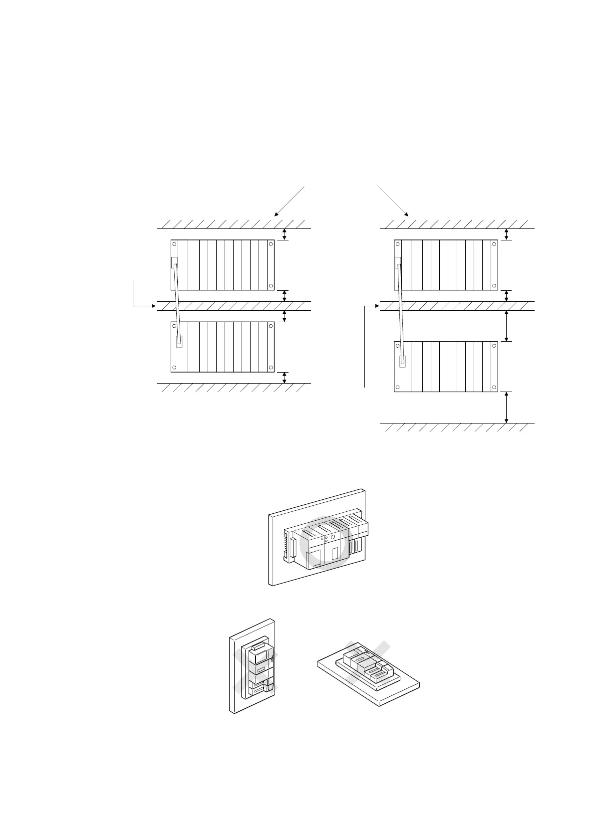
(2) Module installation position
To maintain good ventilation and make it easy to replace the module, keep
the following distances between the top and bottom of the module and the
structure or other components.
A1S3B, A1S38HB, A1S38HBEU, A1S5B(S1), A1S6B(S1)
........................................................................................30 mm (1.18 inch) or over
A5B, A6B..................................................................80 mm (3.15 inch) or over
This shows the position of the panel's ceiling,
wiring duct, or components.
Duct (Height of
50mm (1.97inch)
or less)
Main base
30mm
(1.18inch)
or more
Extension base unit
(A1S5B (S1),
A1S6B(S1))
30mm (1.18inch)
or more
30mm (1.18inch)
or more
30mm (1.18inch)
or more
Main base
30mm
(1.18inch
or more
Extension base unit
(A5
B (S1), A6
B(S1))
Duct (Height of
50mm (1.97inch)
or less)
or more
30mm
(1.18inch)
80mm
(3.15inch)
or more
80mm
(3.15inch)
or more
(3) Module installation direction
(a) Use the programmable controller in the following position for better
ventilation and heat dissipation:
(b) Do not use the programmable controller in the following positions:
Vertical position Horizontal position
(4) Install the base unit on a level surface.
If the surface is not level, force may be applied to the printed wiring board,
causing a malfunction.
 Loading...
