35
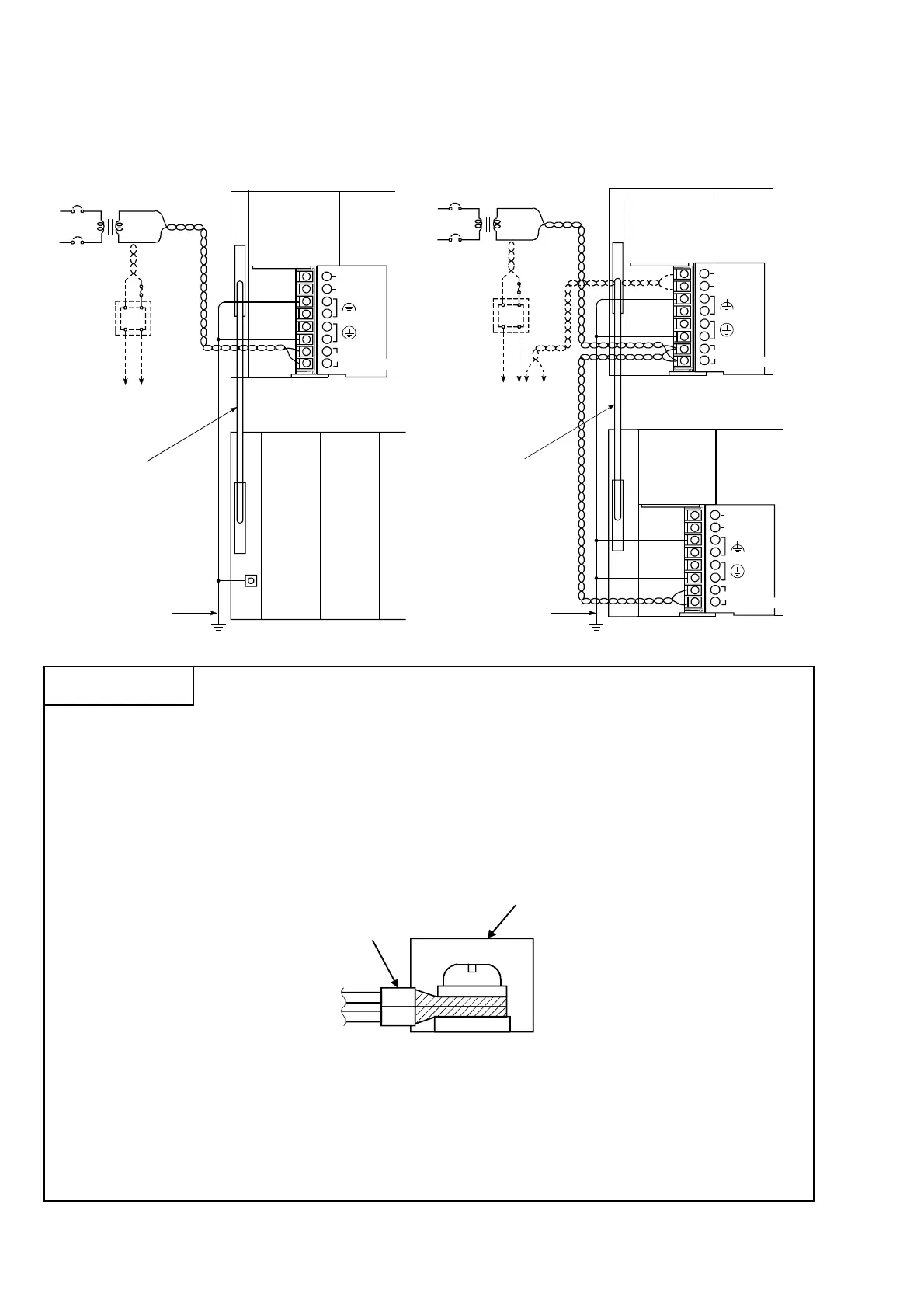
4.3.4 Wiring to module terminals
This section explains the wiring of power lines and grounding lines to the main
and extension bases.
External base unit (A1S58B)
C
100/110VAC
200/220VAC
Fuse
24VDC
AC
DC
Connect to the 24VDC
terminals of an I/O module
that requires 24VDC
internally.
External cable
Main base unit (A1S38B)
A1S61PN
CPU
NC
NC
(FG)
(LG)
INPUT
100-240VAC
I/O I/O
FG
AC
100/110VAC
200/220VAC
24VDC
24VDC
AC
DC
A1S62PN
CPU
A1S62PN
I/O
100/240VAC
+24V
24G
Grounding wire
Ground
External cable
Fuse
Main base unit (A1S38B)
External base unit (A1S68B)
INPUT
100-240VAC
(FG)
(LG)
+24V
24G
INPUT
100-240VAC
(FG)
(LG)
Connect to the 24VDC
terminals of an I/O
module that requires
24VDC internally.
Grounding wire
Ground
POINT
(1) Use the thickest possible (max. 2 mm
2
(14 AWG)) wires for the 100/200
VAC and 24 VDC power cables. Be sure to twist these wires starting at the
connection terminals. For wiring a terminal block, be sure to use a
solderless terminal. To prevent short-circuit due to loosening screws, use
the solderless terminals with insulation sleeves of 0.8 mm (0.03 inch) or
less thick. The number of the solderless terminals to be connected for one
terminal block are limited to 2.
Terminal block
Solderless terminals
with insulation sleeves
(2) Be sure to ground the LG and FG terminals. Failure to do so may cause
the programmable controller to be susceptible to noise. Note that LG
terminals include the potential as half as that of input voltage; you might
get an electric shock when you touch them.
(3) A1S61PN and A1S62PN do not need to be switched as the are 100 to
240VAC wide-range.
 Loading...
