29
4.3.2 Parts names
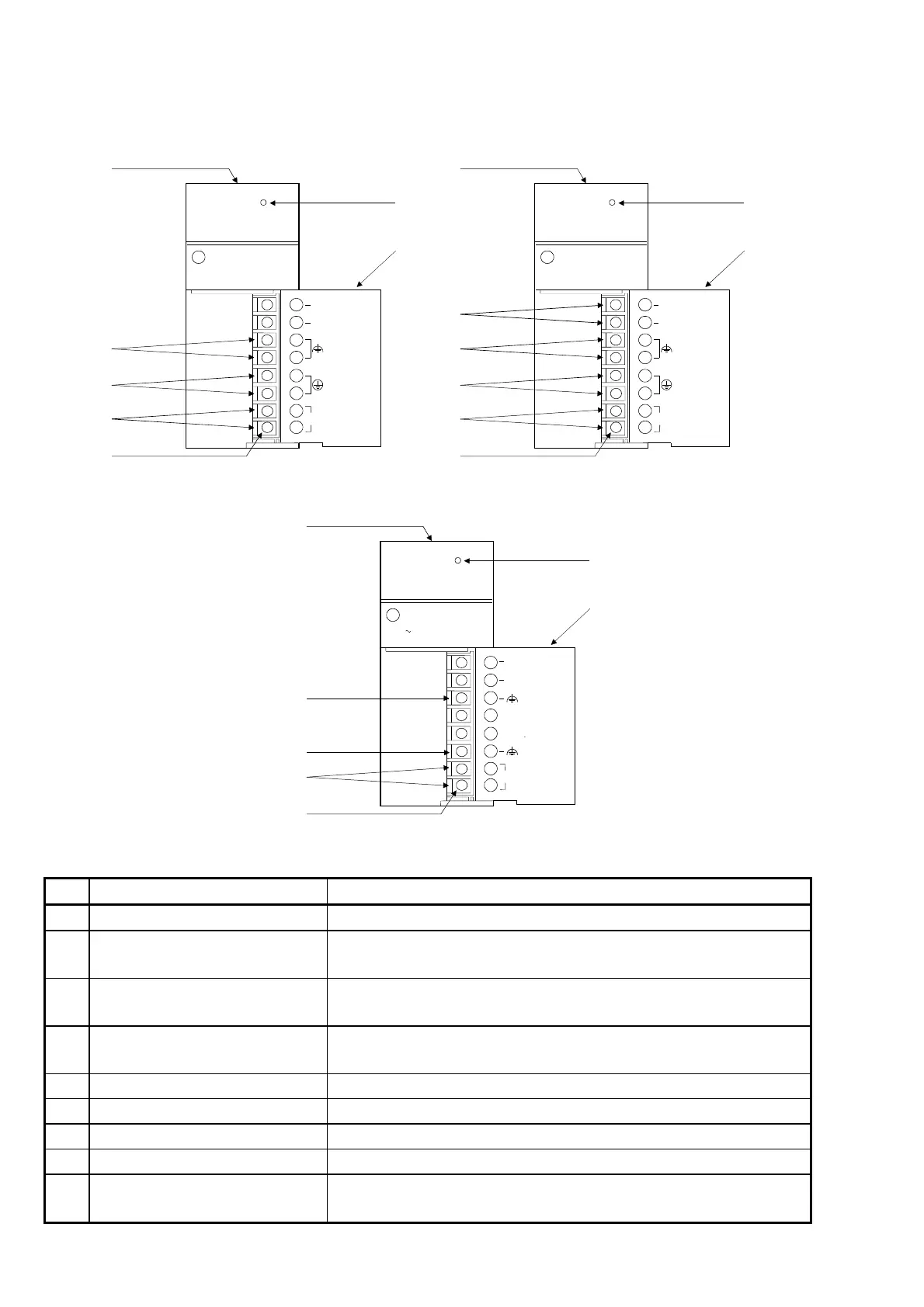
The following gives the names and description of the parts of the power supply
modules:
MELSECA1S61PN
POWER
MITSUBISHI
INPUT
100-240VAC
105VA
50 / 60Hz
OUTPUT
5VDC 5A
INPUT
100-240VAC
[9]
[1]
[6]
[7]
[8]
(LG)
A1S61PN
[4]
[3]
MELSECA1S62PN
POWER
MITSUBISHI
INPUT
100-240VAC
105VA
50 / 60Hz
OUTPUT
5VDC 3A
24VDC 0.6A
+24V
24G
INPUT
100-240VAC
[9]
[1]
[2]
[6]
[7]
[8]
(LG)
A1S62PN
[4]
[3]
NC
NC
MELSECA1S63P
POWER
MITSUBISHI
INPUT
DC15.6 31.2V
OUTPUT
DC 5V 5A
[9]
[1]
[3]
[4]
[5]
[7]
[6]
INPUT
+24V
24G
NC
NC
(1) A1S61PN (2) A1S62PN
(3) A1S63P
(FG)(FG)
(FG)
(LG)
No. Name Description
[1] POWER LED The indicator LED for the 5 V DC power.
[2] 24 V and 24 G terminals
Used to supply 24 V DC to inside the output module
(using external wiring).
[3] FG terminal
The grounding terminal connected to the shield pattern of the
printed circuit board.
[4] LG terminal
Grounding for the power supply filter. The potential of A1S61PN
or A1S62PN terminal is 1/2 of the input voltage.
[5] Power supply input terminals Used to connect a 24 V DC power supply.
[6] Power supply input terminals Used to connect 100 V AC to 200 V AC power supply.
[7] Terminal screw M3.5 × 7
[8] Terminal cover The protective cover of the terminal block.
[9] Module fixing screw
Used to fix the module to the base unit.
(M4 screw, tightening torque: 78 to 118 N⋅cm)
 Loading...
