10
Point
(1) Depending on the type of module used, the settings for D/A module
output range are shown below.
• Q62DAN, Q64DAN .... 0
H
to 4
H
, F
H
• Q68DAVN.................. 0
H
, 2
H
to 4
H
, F
H
1:When the setting is 0
H
, the output operating
range swill be 1 to 5 V.
• Q68DAIN.................... 0
H
, 1
H
, F
H
(2) For Q62DAN and Q64DAN, leave the switch2 vacant.
(3) For Q68DAVN and Q68DAIN, the switch 3 will set in binary.
Setting will be easy if the input format is changed to binary number.
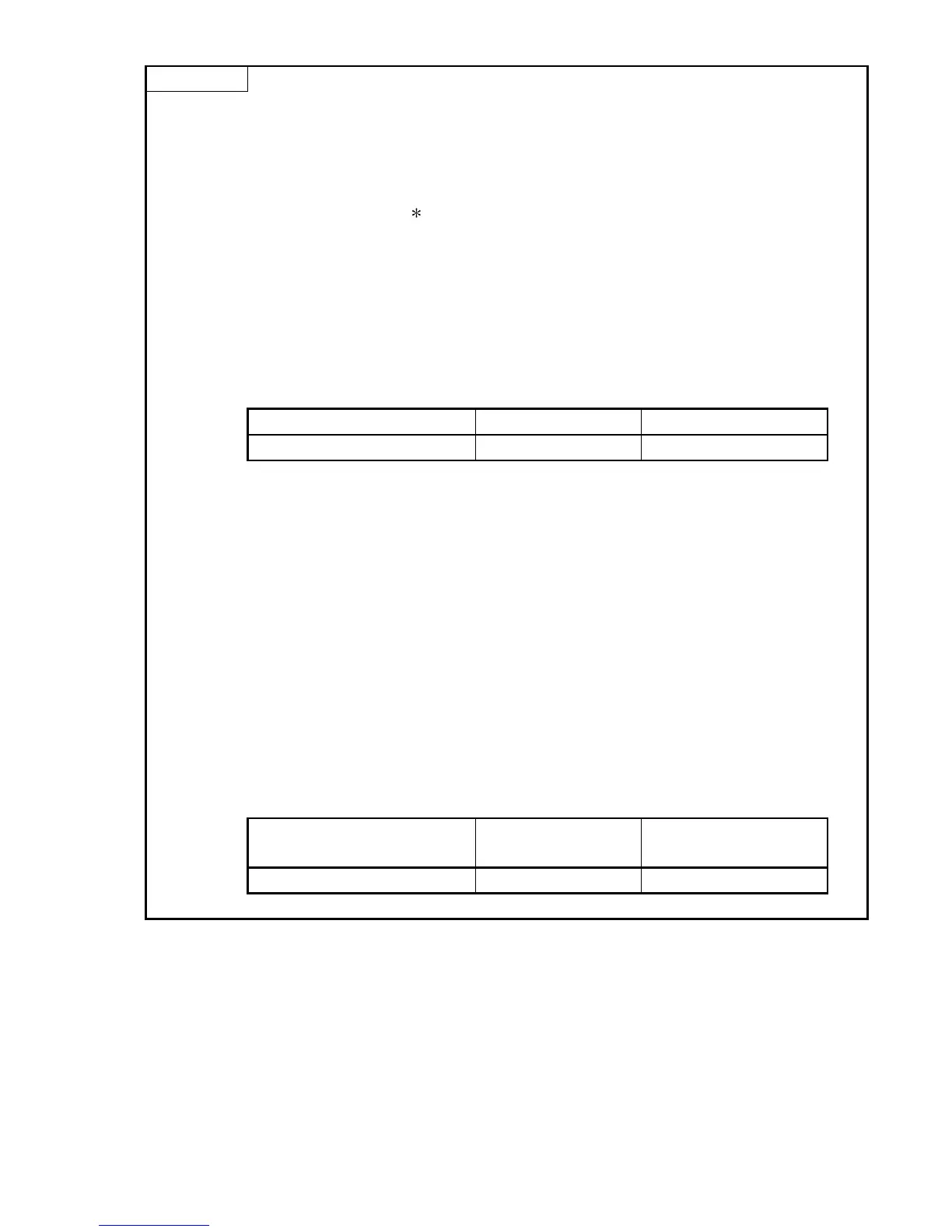
Example) For setting CH3, CH5 and CH8 to HOLD.
Input format Binary Hexadecimal
Setting value 10010100 94
H
(4) If the offset/gain setting mode is set using intelligent function module
switch 4, other settings by switch 4 (settings for resolution mode and
synchronous output mode) will be ignored.
(5) Perform the offset/gain settings after checking the RUN LED flashes in
offset/gain setting mode. If the RUN LED does not flash, check to see if
the switch 4 setting is correct.
(6) Since the analog output value will differ considerably, depending on the
resolution mode setting, thoroughly check the settings for the intelligent
function module switches before performing the analog output
processing.
Example) Analog output value when the setting range is -10 to 10V and
the digital input value is set to 4000.
High resolution
mode
Normal resolution
mode
Analog output value About 2.5 V About 10.0 V

 Loading...