2 - 7 2 - 7
MELSEC-Q
2 SYSTEM CONFIGURATION
2.3 Multiplexed Remote I/O Network for Redundant System (QnPRHCPU Only)
2.3.1 Configuration
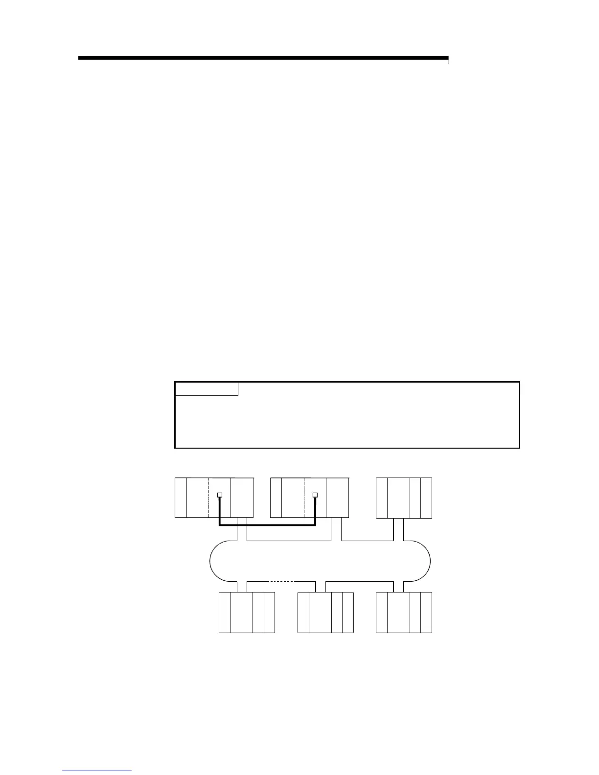
The redundant system including QnPRHCPU utilizes the multiplexed remote I/O
network system in order to control I/O modules and intelligent function modules.
In the multiplexed remote I/O network system for the redundant system, the network
module on the side of the control QnPRHCPU (started up as a control system) acts as
a multiplexed remote master station and controls remote I/O stations, while the
network module mounted on the side of the standby QnPRHCPU performs the sub-
master operation as a multiplexed remote sub-master station.
When the control system CPU or the multiplexed remote master station goes down,
the multiplexed remote sub-master station switches from "standby" to "control" and
takes over the control of the remote I/O stations.
Make sure to assign No.0 to the network module mounted on the system A, i.e., the
system to which the system A connector of tracking cable is connected within the
redundant system.
For station No. of the multiplexed remote sub-master station, set any of No. 1 to 64,
which should not be overlapped with any of remote I/O stations.
The number of remote I/O stations connectable to a multiplexed remote I/O network for
the redundant system is 63 in the optical loop system and 31 in the coaxial bus
system.
POINT
The CPU module applicable for the multiplexed remote master or sub-master
station in the redundant system is the QnPRHCPU only.
The Q02CPU, Q02HCPU, Q06HCPU, Q12HCPU, Q25HCPU, Q12PHCPU and
Q25PHCPU are not applicable.
Power supply
QnPRH
CPU
QJ71
LP21
Station No. 2
(Remote I/O station)
I/O
QJ72
LP25
I/O
Station No. 0
(Multiplexed remote master station)
I/O
QJ72
LP25
I/O
Station No. 4
(Remote I/O station)
I/O
QJ72
LP25
I/O
Station No. 3
(Remote I/O station)
Power supply
I/O
QJ72
LP25
I/O
Station No. 64
(Remote I/O station)
Optical fiber cable
Station No. 1
(Multiplexed remote sub-master station)
QnPRH
CPU
QJ71
LP21
Tracking cable
System
A
Power supply
Power supply
Power supply
Power supply
System
B
In the optical loop system, up to 63 remote I/O stations can be connected.
Connection of up to 31 stations is allowed for the coaxial bus system.
 Loading...


