-
17
-
'18 • SRK-T-250
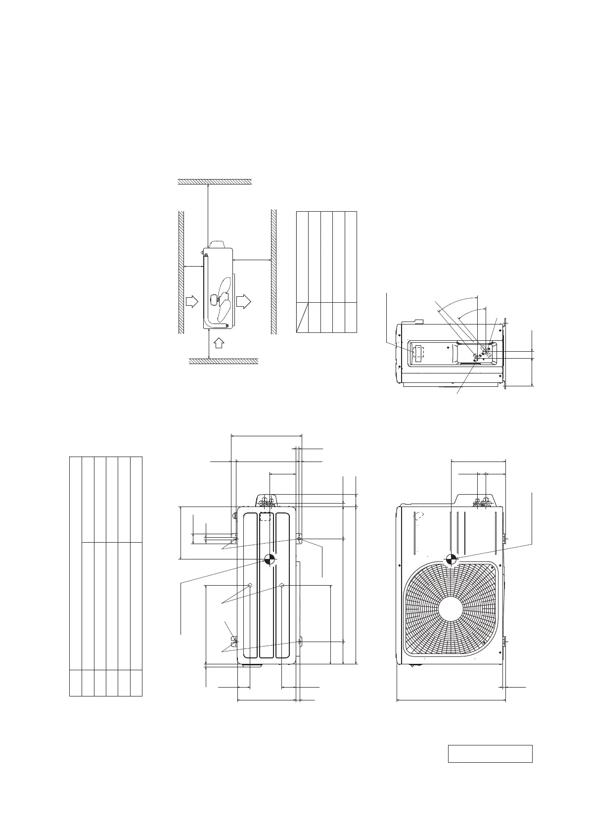
Hole on wall for right rear piping
Hole on wall for left rear piping
Gas piping
Outlet for piping(on both side)
Drain hose
F
E
C
D
Symbol
A
(φ65)
VP16
Content
(φ65)
SRK20, 25, 35 φ9.52(3/8")(Flare)
Wireless remote control
SRK50 φ12.7(1/2")(Flare)
Wired remote control
(Option)
φ6.35(1/4")(Flare)
Liquid piping
B
Space for installation and service when viewing from the front
Unit:mm
Notes(1)The model name label is attached
on the right side of the unit.
(2)To connect the wired remote control,
the interface kit(SC-BIKN2-E)is required.
□120
19
60 24
167
45
45
870
290
Outlet for downward piping
(Refer to the top view)
230 3
6013
530
450
185
190
43
170
585
13
(Service space)
Unit
(Service space)
(Service space)
Installation board
142.5 142.5
100
50
9
47
268
47
80 100
Terminal block
60 3535 60
□120 19
210
55 55
537
528
SRK 50 :475
(Service space)
170
210
435 435
SRK 20,25,35 :469
45
F
D E
A
B
C
F F
φ9.52(3/8")
(Flare)
Content
C Pipe/cable draw-out hole
D
E Anchor bolt hole
Drain discharge hole
Symbol
B
A Service valve connection(gas side)
M10-12×4 places
φ20×2 places
Service valve connection(liquid side)
φ6.35(1/4")
(Flare)
Unit:mm
L2
Inlet
Outlet
Inlet
L3
L1
Service
space
( )
L4
L2
L3
L4
L1
100 or more
80 or more
250 or more
280 or more
Terminal block
2-12×16
Slot hole
2-R
Installation space
63.4
390.6
390.6
69.4
111.6 510 158.4
780 61.9
17.9
14.8 312.5 24.3
351.6
50.6
12
97.7 42.5
40°
40°
138.4 33.5
15.8
290540 20
14.6
16.4
260
130
270
Center of gravity
Center of gravity
Notes
(1) The unit must not be surrounded by walls on the four sides.
(2) The unit must be fixed with anchor bolts. An anchor bolt must not
protrude more than 15mm.
(3) If the unit is installed in the location where there is a possibility of
strong winds, place the unit such that the direction of air from the
outlet gets perpendicular to the wind direction.
(4) Leave 200mm or more space above the unit.
(5) The wall height on the outlet side should be 1200mm or less.
(6) The model name label is attached on the right side of the unit.
A
B
C
E
D
E
(2) Outdoor units
Models SRC20ZS-W, 25ZS-W, 35ZS-W
RCV000Z036
 Loading...