– 30 –
Installation of outdoor unit
1 Make sure that the unit is stable in installation. Fix the
unit to stable base.
2 When installing the unit at a higher place or where it
could be toppled by strong winds, secure the unit firmly
with foundation bolts, wire, etc.
3 Perfrom wiring, making wire terminal numbers conform
to terminal numbers of indoor unit terminal block.
4 Earth lead wire shall be longer than the other lead wires
for the electrical safety in case of the slipping out of the
cord from the anchorage.
Connect using ground screw located near
mark.
(POWER SUPPLY CODE)
CENELEC code for cables requiring fields cables.
H05RNR3G2.5
Connection of refrigerant pipings
Preparation
Connection of refrigerant piping
Keep the openings of the pipes covered with tapes etc. to prevent dust, sand, etc. from entering them.
¡ Remove the flared nuts.
(on both liquid and gas sides)
¡ Remove the flared nuts.
(on both liquid and gas sides)
¡ Install the removed flared nuts to the pipes to
be connected, then flare the pipes.
Dimension A
Liquid side
(ø6.35): 9.0 (mm)
Gas side
(ø9.52): 13.0 (mm)
(ø12.7): 16.2 (mm)
(ø15.88): 19.4 (mm)
Press
Remove
Remove
(Do not
turn)
Spanner
for fixing
the piping)
1 Indoor unit side
2 Outdoor unit side
1 Indoor unit side
2 Outdoor unit side
• Connect firmly gas and liquid side
pipings by Torque wrench.
• Connect firmly gas and liquid side
pipings by Torque wrench.
Do not apply refrigerating
machine oil to the flared
surface.
CAUTION
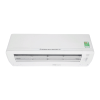
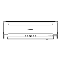
Open/close and detachment/attachment of air inlet panel
1 To open, pull the panel at both ends of lower part and release
latches, then pull up the panel until you feel resistance. (The
air inlet panel stops at approx. 60˚ open position.)
2 To close, hold the panel at both ends of lower part to lower
downward and push it slightly until the latch works, then
push the center portion slightly.
3 To remove, pull up the panel to the position shown in right
illustration and pull it toward you.
4 To install, insert the air inlet panel arm into the slot on the
front panel from the position shown in right illustration, hold
the panel at both ends of lower part, lower it downward
slowly, then push it slightly until the latch works and further
push the center portion slightly.
Approx. 80
To remove / To install
Torque
wrench
• Specified torquing value:
Liquid side (ø6.35) : 14~18N·m (1.4~1.8kgf·m)
Gas side (ø9.52) : 34~42N·m (3.4~4.2kgf·m)
Gas side (ø12.7) : 49~62N·m (4.9~6.2kgf·m)
Gas side (ø15.88) : 68~82N·m (6.8~8.2kgf·m)
• Use one more spanner to fix the valve.
• Always use a Torque wrench and back up spanner
to tighten the flare nut.

 Loading...


