-
104
-
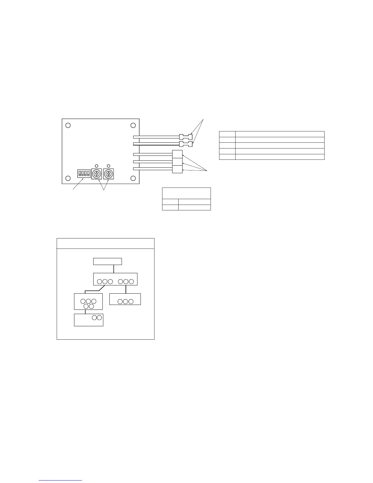
(d) SUPER LINK ADAPTER (SC-AD-E)
(i) Functions
1) Transmits the settings from the Super link option to the indoor units.
2) Returns the priority indoor unit data in response to a data request from the Super link option.
3) Inspects the error status of connected indoor units and transmits the inspection codes to the Super link option.
4) A maximum of 16 units can be controlled (if in the same operation mode).
(ii) Wiring connection diagram
SC-AD-E
A
B
X
Y
Z
X
Y
Z
Blue
Blue
Red
White
Black
Master/Slave address
Network address [00] ~ [47]
Connection to super link
(total length of wires: 1000 m maximum)
0.75 ~ 2.0 mm
2
2-core
Connection to the terminal block for remote control (polar)
(total length of wires: 600 m maximum)
No. Name ot the recommended signal wire
1 Shielding wire
2 Vinylcabtire round cord
3 Vinyl cabtire round cable
4 Control vinyl insulated, vinyl sheath cable
Master/Slave Address
SW 3-1
ON Master
OFF Slave
Shielding wires:
100 ~ 200 m ................. 0.5 mm
2
× 3-core wires
~ 300 m ................. 0.75 mm
2
× 3-core wires
~ 400 m ................. 1.25 mm
2
× 3-core wires
~ 600 m ................. 2.0 mm
2
× 3-core wires
● Make sure to ground one side only of the shielding wire.
1) Set the super link network address with SW1 (10-position) and SW2 (1-position).
2) Without a remote control (no wired remote control and no wireless remote control), set SC-AD-E SW3-1 to ON
(Master).
Outdoor unit
Internal/external Crossing
Indoor unit
Remote control
SC-AD-E
Network
options
X Y Z
X Y
A B
Z
X Y Z
X Y Z
A B
Basic Connections
 Loading...