-
135
-
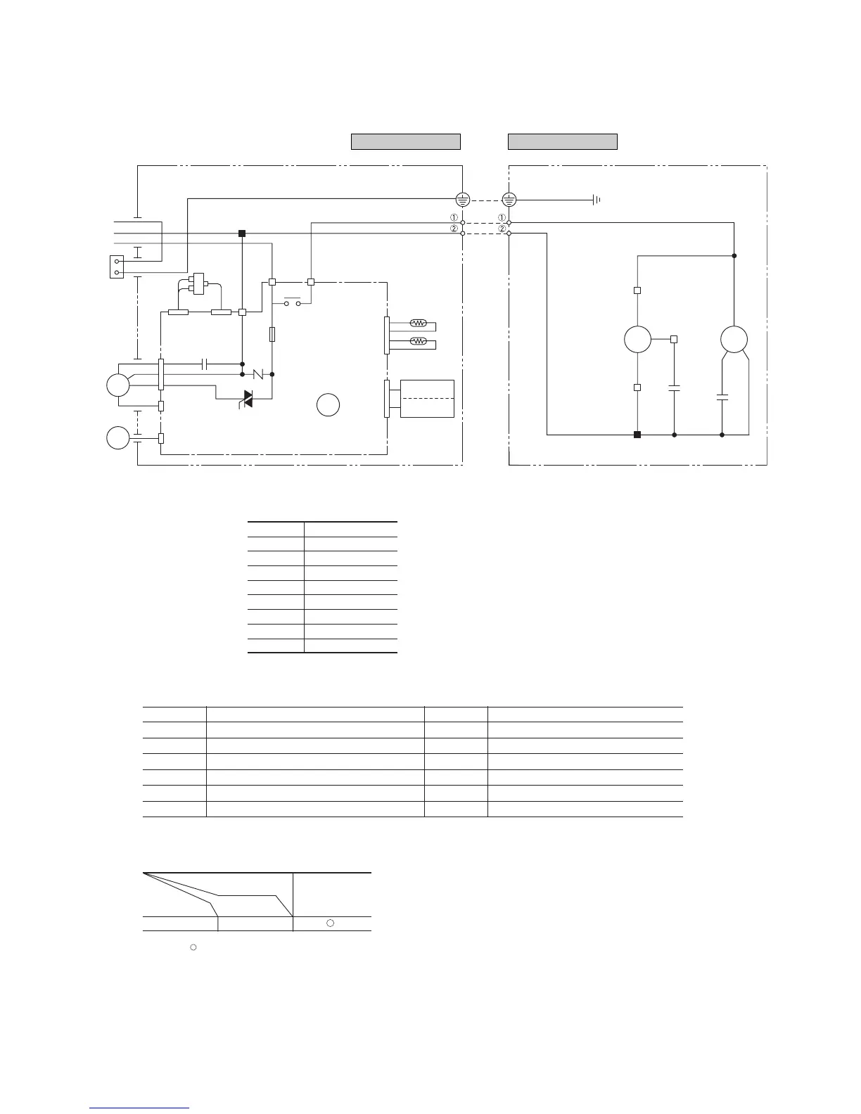
Model SRK13CES
Power source
1 Phase 220V 50Hz
CM
52C
Printed circuit board
FMo
BK
BK
T2
Th
2
T1
Th
1
BK
BKWH
WH
CNC
CNE
CNM CNW
CNU
CNC
Sh1
52C352C4
Tr
N
52C
CNB
Y/GN
LB
Y1
5
3
WH
RD
BR
WH
BK
WH
WH
WH
WH
WH
RD
WH
BK
L2
L3
L1
Sh
CFO
ZNR
F
(3.15A)
CFI
Cc
OR
OR
Wireless
Display
R-Amp
HEAT
EXCHANGER
FM
I
SM
Indoor unit Outdoor unit
Notes (1) : denotes magentized relay
×
: denotes demagnetized relay
(2) Th
1 is room temperature sensor. Th2 (the heat exchanger sensor) is frost prevention sensor.
Operation
Cooling
Relay symbol Control part
52C CM
Table of relay operations
Symbol Parts name Symbol Parts name
C
C
Capacitor for CM FM
O
Fan motor (Outdoor unit)
CF
I
Capacitor for FM
I
SM Flap motor
CF
O
Capacitor for FM
O
Th
1
,
2
Sensor
CM Compressor motor Tr Transformer
F Fuse ZNR Varistor
FM
I
Fan motor (Indoor unit) 52C Magnetic contactor for CM
Meaning of marks
BK Black
BL Blue
BR Brown
LB Light blue
Y Yellow
RD Red
OR Orange
WH White
Y/G Yellow/Green
Color symbol
 Loading...