Printed circuit
board
F2 (250V 20A)
WH
RD
U
V
W
BK
C2
S.IN
R.IN
Re
G
Th4
Th5
Th6
CNB CNE CNA
CND
N
P
Power
transistor
20S
EEV
FMo
DS
CM
BK
WH
RD
Y/GN
1
2
3
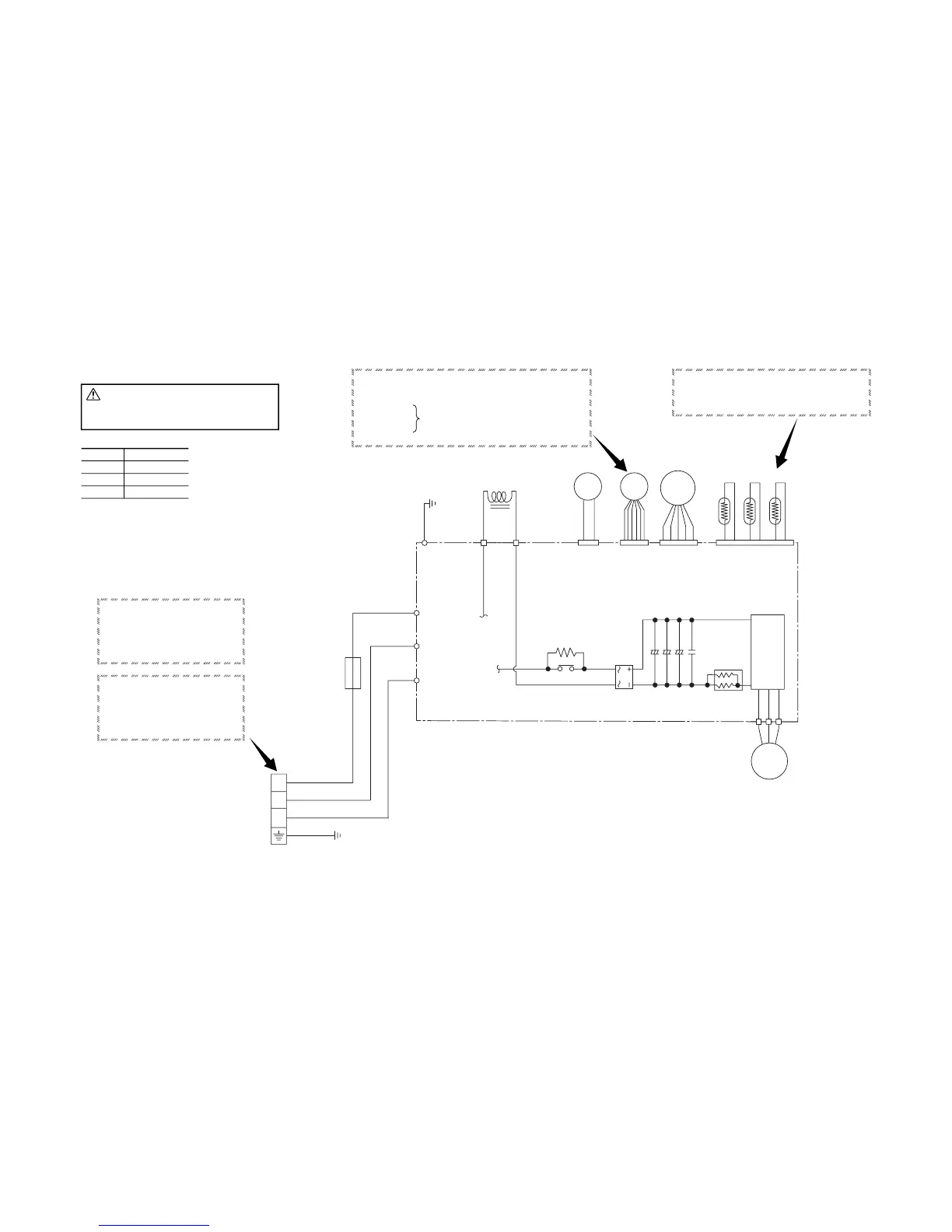
◆ Inspection of resistance value of discharge pipe
sensor
Remove the connector and check the resistance value.
See the section of sensor characteristics on page 36.
◆ Inspection of electronic expansion valve
To test if there is voltage.
◆ Check point of outdoor unit (SRC13ZEV-S)
If the expansion valve does not operate as shown above, it is defective.
(Voltage is only applied to the electronic expansion valve when the valve opening
is being changed.)
Red to White
Red to Orange
Brown to Yellow
Brown to Blue
Normal if there is approximately DC 5 V 10 seconds
after the power asupply is turned on.
Color symbol
BK
RD
WH
Y/GN
Black
Red
White
Yellow/Green
◆ Inspection of input to PCB
¡ Check the voltage between terminals
1~2 on the terminal block.
(It is normal if AC 220V is detected.)
◆ Inspection of serial signal
Check the voltage between terminals
2~3on the terminal block.(It is normal
if the needle swing in the range of DC
0~Approx.12V)
CAUTION
-
HIGH VOLTAGE
High voltage is produced in the control box. Don
’t touch
electrical parts in the control box for 5 minutes after the
unit is stopped.
 Loading...