Do you have a question about the Mitutoyo TM-500 Series and is the answer not in the manual?
Explains visual cues used in the manual for different types of information.
Indicates danger of fire, explosion, or personal injury.
Indicates potential damage or malfunction due to improper operation.
Proper handling and securing of movable members during transport.
Site requirements for installation, considering dirt, dust, humidity, and vibrations.
Warning against operating the microscope in the presence of explosive gas.
Guidance on power supply, voltage stabilization, and avoiding electrical noise.
Instructions for grounding the microscope, especially near noise sources.
Warning against disassembling the instrument due to high internal voltages.
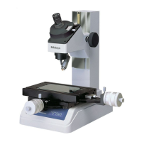
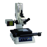
Overview of the TM-500 series Toolmaker's Microscope features and applications.
Identifies all major components of the TM-500 series microscope.
Lists all standard accessories included in the TM-500 series package.
Guidelines for selecting an appropriate installation site, considering vibration and dust.
Procedures for setting up the microscope, including component installation and voltage selection.
Procedures for checking and adjusting the microscope's alignment and calibration.
Procedure to align the reticle with the XY stage movement direction.
Method for centering the reticle relative to the angle dial's center of rotation.
Detailed steps for adjusting reticle alignment with XY stage movement direction.
Method for centering the reticle using adjustment screws for accurate measurements.
Pre-measurement steps including precautions, lens replacement, workpiece fixing, and setup.
Precautions for installation site, operation, objective/eyepiece handling, and stage glass.
Instructions for replacing objectives and eyepieces.
Methods and optional jigs for securing workpieces on the stage.
Explanation of contour illumination, surface illumination, and their combined use.
Steps for replacing reticles using the supplied setting screw.
How to adjust the diopter for sharp reticle visibility.
Procedure for focusing the measuring surface using the focusing knob.
Aligning the workpiece's measuring direction with the stage traverse.
Core measurement procedures for dimensional and angular measurements.
Method for measuring dimensions using the Micrometer Head and cross-hairs.
Procedures for measuring angles using the angle dial.
Using template reticles for inspecting screw threads and gear teeth.
Measuring stepped dimensions using a height measurement attachment.
Procedures for cleaning and lubricating the main unit, XY stage, and optics.
Periodic inspection of various microscope parts and performance.
Checks for focusing knob, XY stage, and angle dial for abnormal operation.
Checks for field of view, stage feeding accuracy, and image resolution.
Procedures for replacing consumable parts like fuses, bulbs, and stage glass.
Steps for replacing the fuse and the stage glass.
Instructions for replacing contour and surface illumination bulbs safely.
Troubleshooting for contour and surface illumination not lighting or having adjustable intensity issues.
Diagnosing issues with optical tube, angle dial, and XY stage movement.
Resolving problems like shadows or poor resolution in the field of view.
Specifications for the optical tube, eyepiece, and objective components.
Dimensions, stage glass size, feeding range, and maximum height for the XY stage.
Specifications for illuminators, mass, and main unit dimensions.
Diagram showing the top view of the TM-505/505R XY stage with dimensions.
Diagram showing the TM-510/510R XY stage with dimensions and T-groove detail.
| Type | Toolmaker's Microscope |
|---|---|
| Objective Magnifications | 5x, 10x |
| Camera Resolution | N/A (microscope only, camera optional) |
| Display | N/A (optical microscope, digital readout optional) |
| Lighting | Halogen lamp |
| Observation Tube | Binocular |
| Minimum Reading | 0.001mm |