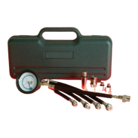
Page Number - 3Form 824255
Always read instructions carefully prior to use.
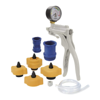
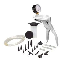
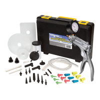
Included in this Kit
• Heavyduty2¾”(70mm)gaugewithhighimpactlens,
rubberboot,andthree(3)scalesofmeasure(psi,
kg/cm
2
,bar),attachedto10”(250mm)hoseandquick
release coupler
• Four(4)extensionhoses:
• 6½”(165mm)longx14mmthread,short
• 12”(305mm)longx14mmthread,short
• 12”(305mm)longx14mmthread,long
• 12”(305mm)longx18mmthread,short
• One(1)adapter:14mmthread,shortx18mmthread,
long
• Two(2)smallengineadapters
• 10mmthread
• 12mmthread
• One(1)quickreleaseairholdadapter
• Customblow-moldedcase
• Fieldservicekit
Applications
The Mityvac Professional Compression Test Kit can per-
form dry or wet compression tests to determine the amount
of pressure produced in the cylinder of an engine. It can
also be used as a tool for pressurizing an engine cylinder
to hold the valves closed while performing repairs.
How to Perform a Comression Test
Precautions & Diagnostic Notes:
WARNING: DO NOT use the ignition switch during the
compression test on fuel-injected vehicles. Use of a
remote starter switch to crank the engine is recom-
mended. Fuel injectors on many late model vehicles
are triggered by the ignition switch during the cranking
mode, this could result in a re hazard or contamina-
tion of the engine’s oil with fuel.
Always use eye protection when performing compres-
sion tests.
An engine in good operating condition will produce a
certainamountofpressureineachcylinder.Normally,
the cylinders should be within 10 percentage points of
oneanotherandwithinthemanufacturer’sspecications.
The pressure should rise smoothly on each stroke of the
engine,untilitreachesapeak.
Ifthepressurereadingfailstorise,oritremainsthesame
forseveralstrokesoftheengineandbeginstorise,the
likely cause of the problem is a sticking valve.
If two adjacent cylinders show pressure readings of 20 or
morepoundsbelowtheothercylinderreadings,suspecta
blown head gasket.
If a cylinder shows a pressure reading of 15 or more
poundshigherthantheothercylinders,theprobablecause
is carbon build-up inside the cylinder.
The Mityvac Professional Compression Test Kit can
performtwotests:thedrycompressiontestandthewet
compression test. The result of performing these tests will
provideanindicationoftheconditionofthepistonrings,the
cylinders,andvalve-train.
Dry Compression Test Procedures:
1. Refer to the appropriate service manual for the com-
pressionspecicationsspecictotheengineyouare
testing.
2. Start engine and allow engine to run until it reaches nor-
mal operating temperature (usually about 15 minutes.)
TurnengineOFF.
3. Install an auxiliary starter switch in the starting circuit.
4. Whilewearingeyeprotection,usecompressedairto
carefully remove dirt and debris from the area around
the spark plugs.
5. Removesparkplugsoneatatime,markingthenumber
ofthecylindertheywereremovedfrom,andplacethem
onacleanatsurface.Thiswillaidyouinidentifying
problem cylinders by allowing the comparison of spark
plug appearance to the compression level of a given
cylinder.
NOTE: When testing engines with two spark plugs
per cylinder, it is only necessary to remove the
spark plugs located on the exhaust side.
6. Onvehicleswithstandarddistributors,disconnectthe
coil wire (high tension lead) from the distributor cap and
secureittoasuitableground,ordisabletheignitionby
disconnecting the positive (BAT) terminal from the igni-
tion coil.
7. Onvehicleswithadistributorlessignition(DIS),disable
the ignition system by removing the electronic ignition
(control)modulefuse,ordisconnectthecrankangle
sensor.
NOTE: Refer to the appropriate service manual to
determine which fuse or component to temporarily
remove or disconnect.
8. Remove air cleaner from carburetor or throttle body and
securethrottlelinkageinwide-openthrottle(WOT)posi-
tion.
NOTE: NEVER place anything inside the throttle
body; internal damage to the engine could result.
On vehicles equipped with port fuel injection,
remove throttle linkage covers (as necessary) and
secure throttle linkage in the wide-open throttle
(WOT) position.
9. Crank engine several times to ensure removal of any for-
 Loading...