MixVibes MAYA 44 SPECIAL EDITION user’s guide
10
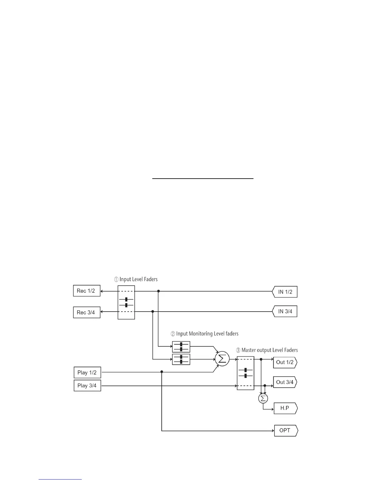
1. Monitor Level Control Section
This section can be used to control the input monitor level. You can monitor the signals
through the input channel 1,2 and input channel 3,4 individually and/or simultaneously. It
will not affect the actual input level from the source. Even if these faders are muted, you
can still record the signals from the source, but you are not able to listen to (= monitor) the
input source through the analog output.
2. Input Level Control Section
This section controls the real input level through the input ports. You can control all 4
inputs using the one set of the stereo faders.
3. Output Level Control Section
These are the master output level faders. You can control all the outputs using the single
set of the stereo master fader, except the digital optical output. You can control the
monitoring level of the input source through the input ports and/or the playing out level of
the wave file through the analog output ports.
Please note that the headphone output signal is the mixed signal from analog out 1, 2 and
analog out 3, 4. Please also note that the analog headphone output and the digital optical
output share the same connector, i.e. they cannot be used simultaneously.
The Gang mode links the left and right faders of each channel together for easier stereo
operation. Deselect Gang if you need to control the left and right levels independently.
Block Diagram
 Loading...