4
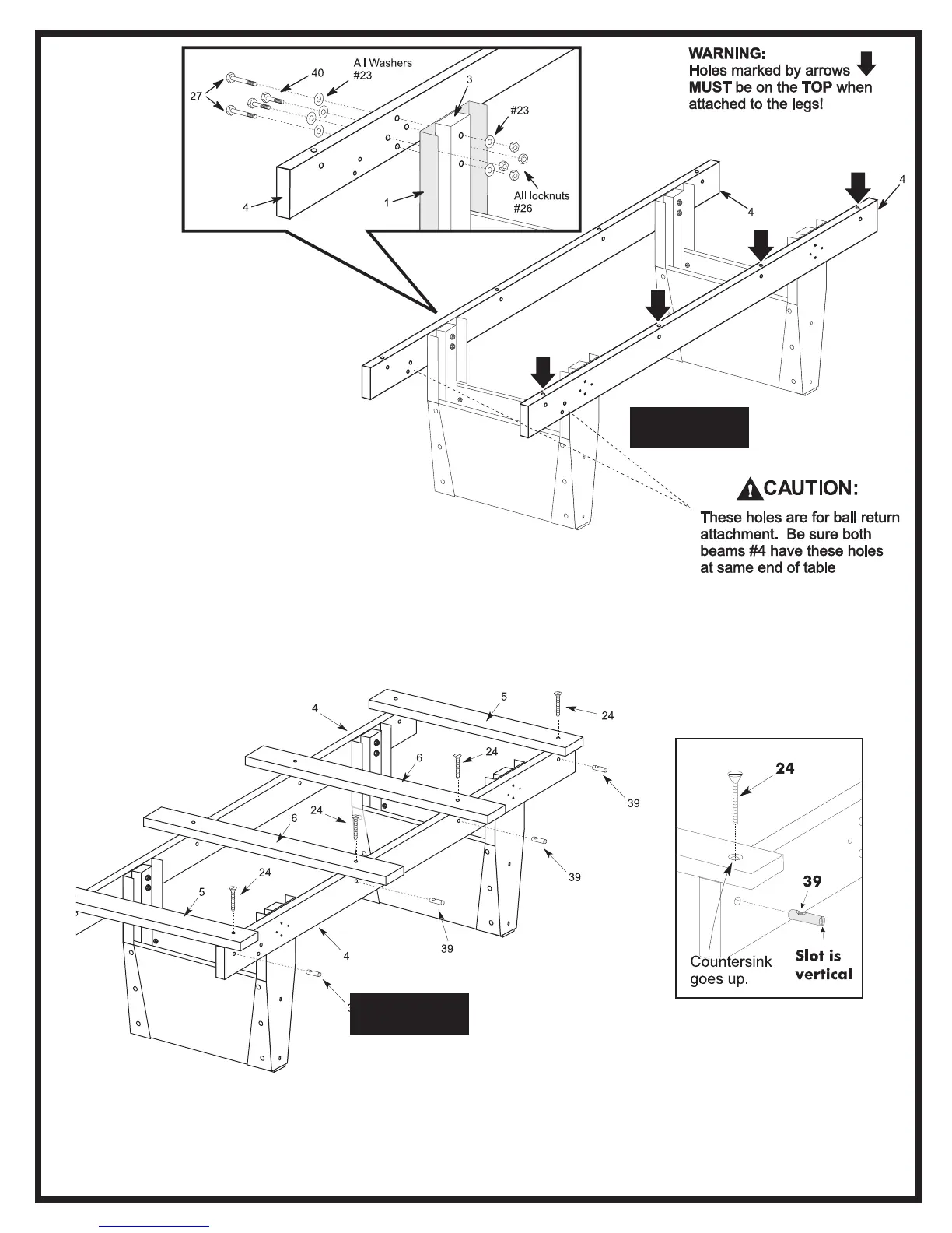
6. Before starting this part of
the assembly, orient beams #4
with ball return attachment holes at
the same end of the table and the
holes marked by arrows in figure 3
facing up.
7. Attach wooden beams #4 to the
leg assemblies (that you just put
together). Use two long bolts #27, two
short bolts #40, six washers #23 and four
locknuts #26 as shown. Repeat for other
beam #4.
NOTE: The two longer bolts #27 go through
top and bottom mounting holes in beam #4, metal
facade #1 and leg post #3. These bolts require a washer
between the bolt and beam #4 as well as between leg post #3 and
the locknut.
NOTE: The two shorter bolts #40 go through the other two mounting
holes in beam #4 and metal facade #1. They only require a washer
between the bolt and beam #4.
Figure 3
Figure 4
Detail A
8. Place slats #5 and #6 across beams #4 as shown
in figure 4. Make sure the two shorter slats #5 go
on the ends of the beams and that the two longer
slats #6 go in the center as shown. The side of the
slats with the countersink around each hole faces
up. (See detail A).
9. Insert four dowel connectors #39 into the holes in
side of beams #4 just below the slats. Note that the
slot in the end of dowel connectors should be
vertical. (See Figure 4 and Detail A). Start screws
#24 the dowel connectors by hand until you are sure
threads are engaged properly. Do not force them
with power tools. Do not tighten screws completely
yet.