Chapter Two: Installation Product Location and Re
uirements
23
Cable Connections
The color code for the interface cables is described in Table 7.
Interface Cable Color Code
Signal Wire Color
+15 VDC Power Input Green
-15 VDC Power Input White
DC Signal* Red
Power Ground (Return) Black
Signal Ground (Return) Black
Chassis (Case) Black (large)
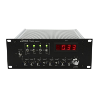
*
At the transducer connector, this signal is referred to as the DC Output while at the PDR-D
connector it is labeled “PRESS IN.”
Table 7: Interface Cable Color Code
Product Location and Requirements
Operating Environmental Requirements
•
Maximum Operating Temperature: 50
°
C (122
°
F)
•
Ventilation requirements include sufficient air circulation
•
Connect the power cord into a grounded outlet
Electrical Information
Grounds
The PDR-D unit has a three ground system which allows for the separation of the power supply
return (P Gnd) and the DC Output Signal return (S Gnd) and the Chassis ground. This is done
primarily for use with the 221 and 221A-B transducers to keep these grounds separate in the
power cable. When used with transducers that have only a two ground system (such as the 220,
222, and 223) connect the P Gnd and S Gnd to that transducer’s common ground and then
connect the two chassis grounds together.



 To Next Page