Chapter Four: Operation General Information
31
Chapter Four: Operation
General Information
1. Connect the PDR-D unit to the pressure transducer. Refer to the instruction manual of
the transducer for the proper input connections.
2. Select the proper decimal point with the front panel decimal switch.
Refer to Figure 2, page 25, for the location of the decimal switch.
3. Apply power to the PDR-D unit.
4. Pump the pressure transducer down to a pressure less than its resolution and check the
zero. Correct if necessary with the front panel zero control.
Refer to Figure 2, page 25, for the location of the zero control.
Theory of Operation
Pressure Signal
The signal is received from the pressure transducer and applied to the input amplifier where the
fine zero correction is applied. The output from this amplifier is applied to the following points:
•
DC Output Terminal
•
4½ Digit Display
•
Overrange Comparator
Overrange Comparator
This circuit monitors the input to the digital display. When this input exceeds
±
11 Volts, this
circuit blanks the display to indicate an overranged condition.
Display and Decimal Selector
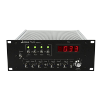
The display receives the pressure signal from the input amplifier. The display is a 4½ digit dual
slope integrating meter with decimal points that are programmed with a 4 pole slide switch. In
the event of an overload, meaning any voltage
≥
11 Volts, the display will be blanked.



 To Next Page