MK8000 EVB Quick Start Guide
Mauna Kea Semiconductor Confidential
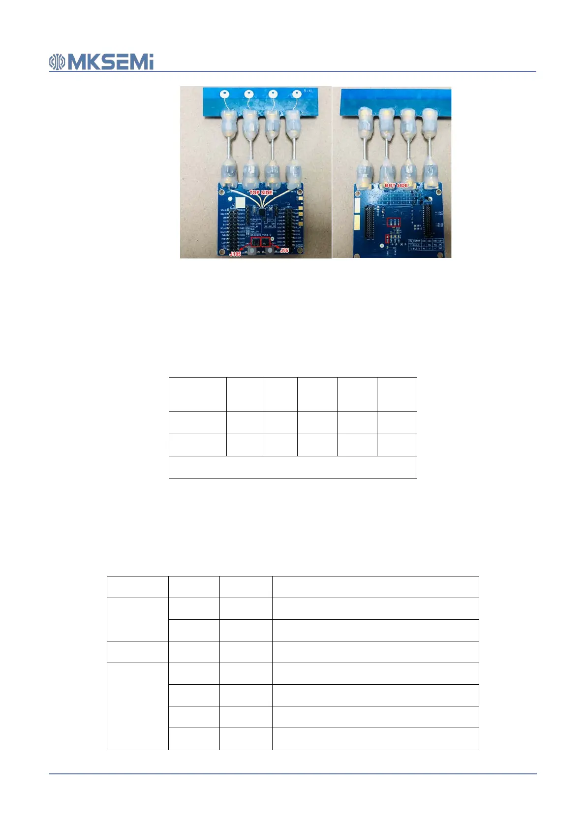
Figure 2 Top and Bot side of MK8000 EVB
Table 1 provides the details of the configuration of the jumpers and the resistor connections for these
two supply voltage options.
Table 1 Jumper configuration for different supply voltage
Supply
voltage
J95 SB1 SB2 SB3 SB4
1.8~3.6v
✔ ✔ ✖ ✖ ✖
3.6v~5.5v
✔ ✖ ✔ ✔ ✖
shorting or connect ‘✔’ disconnect ‘✖’
3.3 Function Description of Jumper Pins
The MK8000 EVB has two rows of jumpers that are connected to the I/Os of the chip to offer the
flexibility of configuration and programming. Table 2 describes the functionality of the jumper pins on
the MK8000 EVB.
Table 2 Jumper Pin Description
Function Jumper Pin Description
SWD
J101 SWDIO SWDIO
J101 SWDCLK SWDCLK
RESET J101 RSTN RESET (active low)
SPI0
J101 IO_14 CSN
J101 IO_13 CLK
J101 IO_12 MISO
J101 IO_11
MOSI