10
EXTERNAL CONNECTORS (top plate)
CONTROL WIRING (LOW VOLTAGE)
RS-232 9 way D connector - for future use.
5 Pin XLR chassis socket for DMX connection.
Connections:- DMX = pin 3, DMX = pin 2, Screen = pin 1.
5 Pin XLR chassis plug for DMX connection.
Connections:- DMX = pin 3, DMX = pin 2, Screen = pin 1.
25mm conduit entry for hard wired control cables.
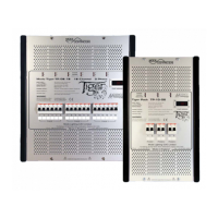
DATA INPUT TERMINALS (for digital control only)
Lever operated screwless terminals
as follows:-
D+ = DMX+
D- = DMX- Inputs
SC = DMX Screen
D+ = DMX+
D- = DMX-
Outputs
SC = DMX Screen
5V = +5V supply to Scenario plate
DT = Scenario Data line
0V = 0V reference
5V = +5V supply to Scenario plate
DT = Scenario Data line
0V
= 0V reference
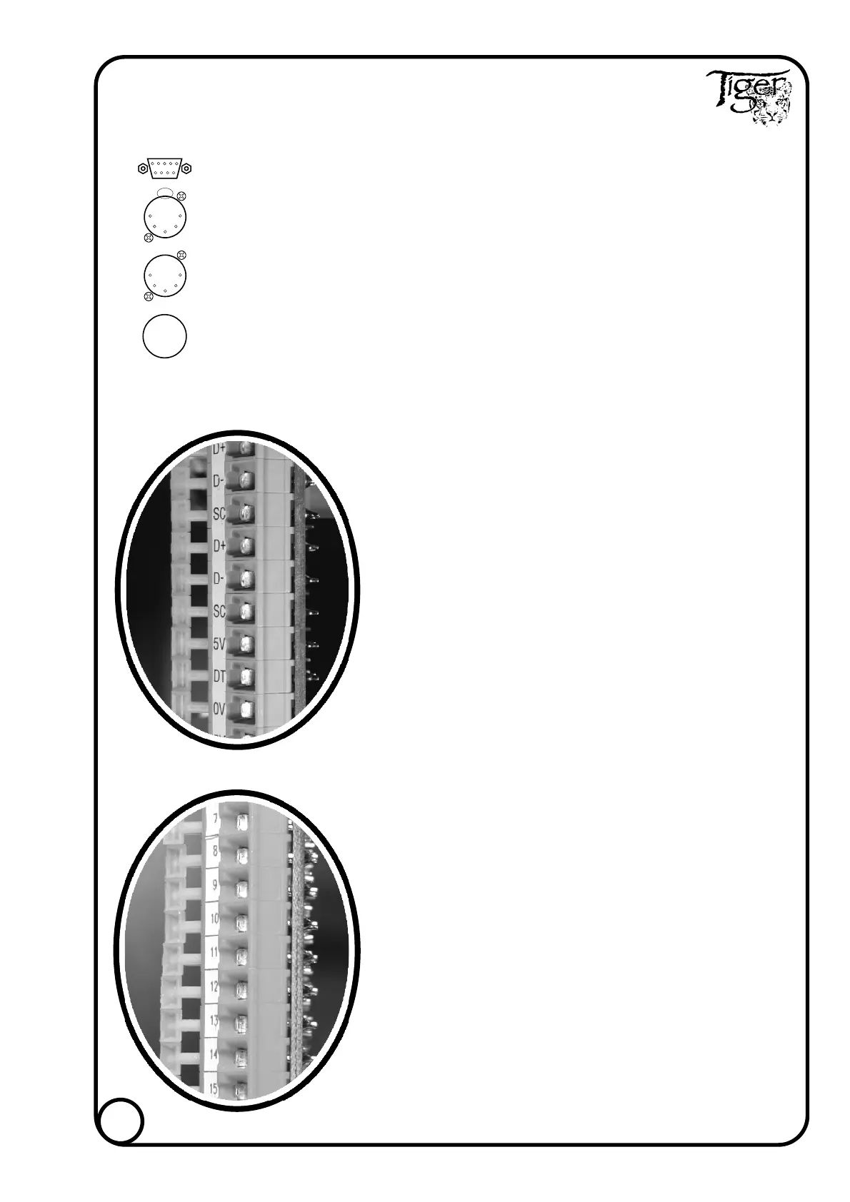
AUXILIARY TERMINALS
15 = +15V DC output to supply remote equipment
AL = Alarm input
TERMINALS 1 - 18
In Digital Mode
These terminals provide either 0 to +6V or 0 to +10V
DC control signals.
Capable of sourcing 50µA and sinking 100mA.
For 6 channel type terminals
07-18 are not used.
For 9 channel type terminals 10-18 are not used.
In Analogue Mode
Terminals 1-9 to be supplied with a DC control signal
of 0 to +6V or 0 to +10V.
For 6 channel type terminals 07-18 are not used.
}
}
+
+
-
-
}
}
Inputs
Outputs